![]()
| I meet a lot of
radio experimenters via my web site. Occasionally, to my delight, some of
these radio enthusiasts want to contribute to the site with ideas and/or
projects. Such is the case of David Forsman, WA7JHZ. I am very pleased to
provide some of his schematics and experimentally developed projects on
the QRPHB web site.
|
|
SSB 75 Meter Transceiver |

|
The 75 Meter QRP SSB Transceiver Theory of Operation 6-30-03 |
| In
general, the transceiver switches the 4-element 1500 ohm xtal BPF ends
between the inputs and outputs of the two SA602s to reverse the signal
flow for R/T operation. Since no IF amplifier is used in the design, 20 dB
of additional receiver gain is produced by the 2N2222 receiver RF
amplifier, while automatic gain control (AGC) is produced by the peak DC
swing of the LM386 output passed through a rectifier and filtered by a
capacitor and fed to the gate of a BS170 enhancement mode FET acting as a
variable resistor across the input of the LM386. Both receive and transmit bandpass filtering are done by the same half-pi BPF. The diode pair in the mic circuit reduce the "chirp" that occurs during the R/T transition. Additional BS170s could easily be used to mute both the mic and audio instead of the R/T switch directly. These BS170s would be controlled by the +R and +T voltages on their gates while their drains would be tied to 1) the mic circuit between the two coupling capacitors and 2) pin number 1 (audio in) of the LM386 (BS170 sources to ground). Additional power output (perhaps 60 mW) could also be attained by connecting the RF output transistor's collector choke (10 uH) to a 9 V supply instead of the 5 V. Additional biasing current might also be required for this change. The R/T switches are from Radio Shack and are of the slider-type with silver plated brass connectors. I removed the detent springs from two of them and weakened the third. I then drilled holes through the switches' handles to connect them with a piece of tempered copper-plated steel wire. The switches are marked on their sides with the word "ALPHA." Low current-drain type DPDT relays (10 to 12 mA @ 12 V) could also be used in place of the switches. I used switches to reduce transmit current, and they work very smoothly. The intent of this design was to minimize the parts count (about 85) and size, reduce power consumption (17 mA receive and 40 mA transmit), run on a 9 V battery, be self contained (except for antenna), have good rejection of unwanted signals, have good sensitivity and selectivity, and have automatic gain control (AGC)--with enough parts left over to build another rig. Finally, the variable tuning capacitor of the local oscillator (LO) could be replaced with a varactor diode circuit. The homebrewer should be able to build this transceiver in a "week of evenings," if all of the parts are available. Should a commercial circuit board version be developed, the circuit could easily be completed in one evening! Good luck with your project. Receive: 50 ohm antenna
feeds half-pi bandpass filter (BPF, element Q=5) which feeds
receive-transmit (R/T) switch which feeds 2N2222 receive RF amplifier
which feeds 1st SA602 which feeds R/T switch which feeds 4-element 1500
ohm xtal BPF which feeds R/T switch which feeds 2nd SA602 which feeds
LM386 which feeds 1) diode which feeds capacitor which feeds gate of BS170
which produces audio automatic gain control (AGC) and 2) speaker
attenuator which feeds speaker. |


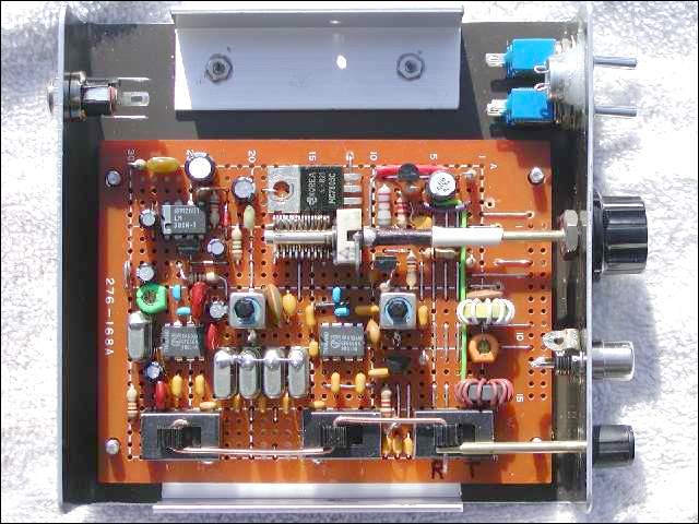
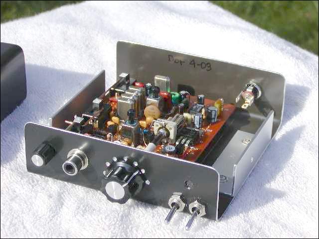
| Below. 2 views of the transceiver prior to final wiring. The
layout is impeccable. |
|
QRP SWR Meter With LED Indicator |

|
Above, a schematic diagram for a broadband QRP SWR metering circuit for use in a QRP antenna tuner. One could simply hold a momentary DPDT switch down and watch the LED while tuning the capacitors of the antenna tuner for minimum or zero light. |
|
QRP Filter Design Software |
|
These are the two synthesis
programs that were written to design the xtal and bandpass filters for the
QRP transceiver. These might be useful for anyone who wants to build the
transceiver for different IF and output frequencies. The seperate files
can be downloaded as individual exe files or combined in one zip file.
These programs are DOS applications and are 36-42 KB file
size. |
|
Phasing Exciter for 75 Meter SSB |

|
Above and below; the schematic
and the outcome project in a complete tranceiver. |

|
Three Frequency Crystal Marker |

|
EMF Field Intensity Meter |

