TRANSMITTER BUILDING BLOCKS
Block Diagram of an SSB Transmitter
OSCILLATORS
CRYSTAL OSCILLATOR
This oscillator works well with fundamental mode crystals up to about 22MHz. Component values were chosen for a frequency of 7.8MHz. See the SSB transceiver project elsewhere on this site.
FET CRYSTAL OSCILLATOR
This FET oscillator will work with both fundamental and 3rd overtone crystals up to about 60MHz
VFO AND BUFFER AMP
Thermal, mechanical and electrical stability are the factors that determine the frequency stability of a VFO. There is no magic circuit that will guarantee good results. There is a bewildering array of circuit designs available, Colpitts, Hartley, Clapp, Seiler, Vakar, Franklin............. Most will give good results if you use the right components.
The Clapp circuit above is a series tuned Colpitts oscillator. I use this VFO in my HF rig. The Inductor (L) is the most critical component in the VFO. I used 1mm enamelled copper wire tightly wound on a ceramic former. A section of a 1KW electric heater element (the type used in old electric fires) makes an excellent coil former. Don't try to drill through the ends. I destroyed several HSS drills before giving up. The ends of the coil can be secured with a small amount of epoxy resin. For the 100p, 470p and 47p capacitors, use polystyrene, NPO ceramic or silvered mica. The tuning capacitor should be air spaced, preferably a double bearing type. Most general purpose N-channel JFets should work in this circuit. I usually use J113's. The 2N3819, BF256, MPF102 etc. should work just as well. This oscillator needs a very stable DC supply. I use 5 volts from a 7805 voltage regulator.
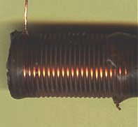
VFO COIL ON CERAMIC FORMER
BAND SWITCHED VFO
It is very difficult to build a stable VFO for frequencies above 10MHz. The mixer VFO is one way of overcoming this problem. The signal from a relatively low frequency VFO is mixed with the signal from a crystal oscillator. For example, a 5MHz VFO could be mixed with the output from a 24MHz crystal oscillator, to produce a signal at 29MHz. The image frequency, 24 - 5 = 19 MHz is removed by a band pass filter.
PHASE LOCKED LOOP OSCILLATORS
20 MHz PLL SYNTHESIZER
LOCKED TO 1.5MHz VFO
The circuit above is a simplified block diagram of a 20MHz PLL synthesizer. The V.C.O. (voltage controlled oscillator) signal is mixed with the output from a 21.5MHz crystal oscillator. The 1.5MHz signal at the mixer output is filtered by a low pass filter, amplified and fed to one input of a phase comparator. The phase comparator and loop filter generates a DC control voltage which is used to control the V.C.O. frequency.
In the example below, the 1.5MHz mixer signal is divided down to 10KHz by a programmable divider. This 10KHz signal is compared with a 10KHz signal from a 10.240MHz crystal oscillator and /1024 fixed divider. By changing the division ratio of the programmable divider, the V.C.O. frequency can be changed in 10KHz steps. This arrangement is widely used in VHF, UHF, and CB radios (a good source of 10.240MHz crystals.) The design of the loop filter is quite critical. The time constant must be short enough to give a reasonably quick loop settling time but be long enough to filter out the 10KHz reference signal. Check Motorola's web site for data sheets. The MC145106 has several of the blocks below, all in one chip.
20 MHz PLL SYNTHESIZER
DDS
DDS SYNTHESIZER
The DDS synthesizer uses a high speed DAC (digital to analogue converter) and a look-up-table of sine/cosine values stored in a ROM (read only memory,) to generate a radio frequency sine wave. A special, variable modulus counter known as a phase accumulator is used to step through the sine wave values in the ROM. The phase accumulator count is incremented by each pulse from the crystal-controlled clock. The number that is added to the count is determined by the frequency control input or 'frequency tuning word'. See the Analog Devices website: www.analog.com for the AD9850 DDS data sheet.
TRANSMIT AMPLIFIERS
LOW LEVEL TRANSMIT AMPLIFIER
Transmit R.F. amplifiers are quite similar to receive R.F. amplifiers. The significant difference is the much higher power levels in TX amplifiers. RX amplifiers are designed to amplify millivolts, TX amplifiers must handle volts!
TWO STAGE TRANSMIT AMPLIFIER
This amplifier from the SSB transceiver project trx.html has a gain of about 30dB.
P.A. and driver from the 2M CW transmitter project 2m.html
TX MIXERS
I.C. TRANSMIT MIXER
This is a typical I.C.transmit mixer. The Plessey SL1640 is now obsolete. Other I.C.'s that can be used as TX mixers include:
SL6440, SO42P, MC1496, CA3028, AD831.
The diode double balanced mixer makes an excellent transmit mixer. See receiver building blocks page for more info. rx_circ.html
SIMPLIFIED BLOCK DIAGRAM OF AN SSB TRANSMITTER