Table Of Contents
Using the Border Gateway Protocol for Interdomain Routing
Multi-Exit Discriminator Attribute
Summary of the BGP Path Selection Process
Controlling the Flow of BGP Updates
12
Using the Border Gateway Protocol for Interdomain Routing
The Border Gateway Protocol (BGP), defined in RFC 1771, provides loop-free interdomain routing between autonomous systems. (An autonomous system [AS] is a set of routers that operate under the same administration.) BGP is often run among the networks of Internet service providers (ISPs). This case study examines how BGP works and how you can use it to participate in routing with other networks that run BGP. The following topics are covered:
•
Controlling the Flow of BGP Updates
Note
BGP Fundamentals
This section presents fundamental information about BGP, including the following topics:
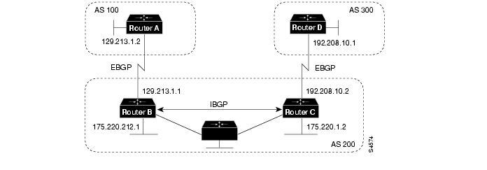
Routers that belong to the same AS and exchange BGP updates are said to be running internal BGP (IBGP), and routers that belong to different ASs and exchange BGP updates are said to be running external BGP (EBGP). With the exception of the neighbor ebgp-multihop router configuration command (described in the section " External BGP" later in this chapter), the commands for configuring EBGP and IBGP are the same. This case study uses the terms EBGP and IBGP as a reminder that, for any particular context, routing updates are being exchanged between ASs (EBGP) or within an AS (IBGP).
shows a network that demonstrates the difference between EBGP and IBGP.
Figure 12-1 EBGP, IBGP, and Multiple ASs
Before it exchanges information with an external AS, BGP ensures that networks within the AS are reachable. This is done by a combination of internal BGP peering among routers within the AS and by redistributing BGP routing information to Interior Gateway Protocols (IGPs) that run within the AS, such as Interior Gateway Routing Protocol (IGRP), Intermediate System-to-Intermediate System (IS-IS), Routing Information Protocol (RIP), and Open Shortest Path First (OSPF).
BGP uses the Transmission Control Protocol (TCP) as its transport protocol (specifically port 179). Any two routers that have opened a TCP connection to each other for the purpose of exchanging routing information are known as peers or neighbors. In , Routers A and B are BGP peers, as are Routers B and C, and Routers C and D. The routing information consists of a series of AS numbers that describe the full path to the destination network. BGP uses this information to construct a loop-free map of ASs. Note that within an AS, BGP peers do not have to be directly connected.
BGP peers initially exchange their full BGP routing tables. Thereafter, BGP peers send incremental updates only. BGP peers also exchange keepalive messages (to ensure that the connection is up) and notification messages (in response to errors or special conditions).
In , the following commands configure BGP on Router A:
router bgp 100neighbor 129.213.1.1 remote-as 200The following commands configure BGP on Router B:
router bgp 200neighbor 129.213.1.2 remote-as 100neighbor 175.220.1.2 remote-as 200The following commands configure BGP on Router C:
router bgp 200neighbor 175.220.212.1 remote-as 200neighbor 192.208.10.1 remote-as 300The following commands configure BGP on Router D:
router bgp 300neighbor 192.208.10.2 remote-as 200The router bgp global configuration command enables a BGP routing process and assigns to it an AS number.
The neighbor remote-as router configuration command adds an entry to the BGP neighbor table specifying that the peer identified by a particular IP address belongs to the specified AS. For routers that run EBGP, neighbors are usually directly connected, and the IP address is usually the IP address of the interface at the other end of the connection. (For the exception to this rule, see the section " EBGP Multihop," later in this chapter.) For routers that run IBGP, the IP address can be the IP address of any of the router's interfaces.
Note the following about the ASs shown in :
•
•
•
To verify that BGP peers are up, use the show ip bgp neighbors EXEC command. Following is the output of this command on Router A:
RouterA# show ip bgp neighborsBGP neighbor is 129.213.1.1, remote AS 200, external linkBGP version 4, remote router ID 175.220.212.1BGP state = established, table version = 3, up for 0:10:59Last read 0:00:29, hold time is 180, keepalive interval is 60 secondsMinimum time between advertisement runs is 30 secondsReceived 2828 messages, 0 notifications, 0 in queueSent 2826 messages, 0 notifications, 0 in queueConnections established 11; dropped 10Anything other than state = established indicates that the peers are not up. The remote router ID is the highest IP address on that router (or the highest loopback interface, if there is one). Notice the table version number: each time the table is updated by new incoming information, the table version number increments. A table version number that continually increments is an indication that a route is flapping, thereby causing routes to be updated continually.
Note
Internal BGP
Internal BGP (IBGP) is the form of BGP that exchanges BGP updates within an AS. Instead of IBGP, the routes learned via EBGP could be redistributed into IGP within the AS and then redistributed again into another AS. However, IBGP is more flexible, provides more efficient ways of controlling the exchange of information within the AS, and presents a consistent view of the AS to external neighbors. For example, IBGP provides ways to control the exit point from an AS.
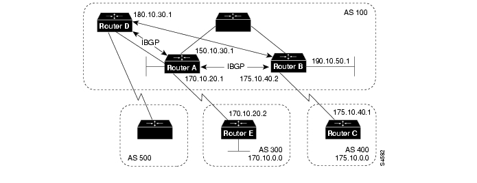
shows a topology that demonstrates IBGP.
Figure 12-2 Internal BGP Example
The following commands configure Routers A and B in AS 100, and Router C in AS 400:
!Router Arouter bgp 100neighbor 180.10.30.1 remote-as 100neighbor 190.10.50.1 remote-as 100neighbor 170.10.20.2 remote-as 300network 150.10.0.0!Router Brouter bgp 100neighbor 150.10.30.1 remote-as 100neighbor 175.10.40.1 remote-as 400neighbor 180.10.30.1 remote-as 100network 190.10.50.0!Router Crouter bgp 400neighbor 175.10.40.2 remote-as 100network 175.10.0.0!Router Drouter bgp 100neighbor 150.10.30.1 remote-as 100neighbor 190.10.50.1 remote as 100network 190.10.0.0When a BGP speaker receives an update from other BGP speakers in its own AS (that is, via IBGP), the receiving BGP speaker uses EBGP to forward the update to external BGP speakers only. This behavior of IBGP is why it is necessary for BGP speakers within an AS to be fully meshed.
For example, in , if there were no IBGP session between Routers B and D, Router A would send updates from Router B to Router E but not to Router D. If you want Router D to receive updates from Router B, Router B must be configured so that Router D is a BGP peer.
Loopback Interfaces
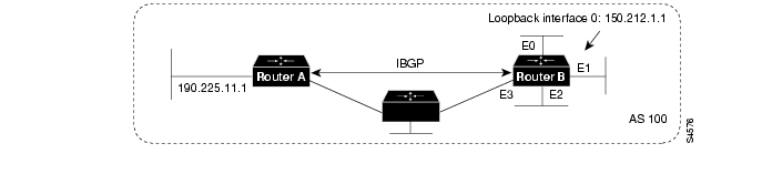
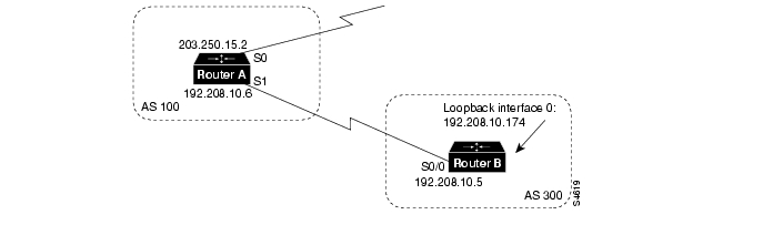
Loopback interfaces are often used by IBGP peers. The advantage of using loopback interfaces is that they eliminate a dependency that would otherwise occur when you use the IP address of a physical interface to configure BGP. shows a network in which using the loopback interface is advantageous.
Figure 12-3 Use of Loopback Interfaces
In , Routers A and B are running IBGP within AS 100. If Router A were to specify the IP address of Ethernet interface 0, 1, 2, or 3 in the neighbor remote-as router configuration command, and if the specified interface were to become unavailable, Router A would not be able to establish a TCP connection with Router B. Instead, Router A specifies the IP address of the loopback interface that Router B defines. When the loopback interface is used, BGP does not have to rely on the availability of a particular interface for making TCP connections.
The following commands configure Router A for BGP:
!Router Arouter bgp 100neighbor 150.212.1.1 remote-as 100The following commands configure Router B for BGP:
!Router Bloopback interface 0ip address 150.212.1.1 255.255.0.0!router bgp 100neighbor 190.225.11.1 remote-as 100neighbor 190.225.11.1 update-source loopback 0Router A specifies the IP address of the loopback interface (150.212.1.1) of Router B in the neighbor remote-as router configuration command. This use of the loopback interface requires that the configuration of Router B include the neighbor update-source router configuration command. When the neighbor update-source command is used, the source of BGP TCP connections for the specified neighbor is the IP address of the loopback interface instead of the IP address of a physical interface.
Note
External BGP
When two BGP speakers that are not in the same AS run BGP to exchange routing information, they are said to be running EBGP. This section describes commands that solve configuration problems that arise when BGP routing updates are exchanged between different ASs:
EBGP Multihop
Usually, the two EBGP speakers are directly connected (for example, over a wide-area network [WAN] connection). Sometimes, however, they cannot be directly connected. In this special case, the neighbor ebgp-multihop router configuration command is used.
Note
illustrates a topology in which the neighbor ebgp-multihop command is useful.
Figure 12-4 EBGP Multihop
The following commands configure Router A to run EBGP:
!Router Aloopback interface 0ip address 129.213.1.1!router bgp 100neighbor 180.225.11.1 remote-as 300neighbor 180.225.11.1 ebgp-multihopneighbor 180.225.11.1 update-source loopback 0The neighbor remote-as router configuration command specifies the IP address of an interface that is an extra hop away (180.225.11.1 instead of 129.213.1.3), and the neighbor ebgp-multihop router configuration command enables EGBP multihop. Because Router A references an external neighbor by an address that is not directly connected, its configuration must include static routes or must enable an IGP so that the neighbors can reach each other.
The following commands configure Router B:
!Router Bloopback interface 0ip address 180.225.11.1router bgp 300neighbor 129.213.1.1 remote-as 100neighbor 129.213.1.1 ebgp-multihopneighbor 129.213.1.1 update-source loopback 0EBGP Load Balancing
The neighbor ebgp-multihop router configuration command and loopback interfaces are also useful for configuring load balancing between two ASs over parallel serial lines, as shown in .
Figure 12-5 Load Balancing over Parallel Serial Lines
Without the neighbor ebgp-multihop command on each router, BGP would not perform load balancing in , but with the neighbor ebgp-multihop command on each router, BGP uses both serial lines. The following commands configure load balancing for Router A:
!Router Ainterface loopback 0ip address 150.10.1.1 255.255.255.0!router bgp 100neighbor 160.10.1.1 remote-as 200neighbor 160.10.1.1 ebgp-multihopneighbor 160.10.1.1 update-source loopback 0network 150.10.0.0!ip route 160.10.0.0 255.255.0.0 1.1.1.2ip route 160.10.0.0 255.255.0.0 2.2.2.2The following commands configure load balancing for Router B:
!Router Binterface loopback 0ip address 160.10.1.1 255.255.255.0!router bgp 200neighbor 150.10.1.1 remote-as 100neighbor 150.10.1.1 ebgp-multihopneighbor 150.10.1.1 update-source loopback 0network 160.10.0.0!ip route 150.10.0.0 255.255.0.0 1.1.1.1ip route 150.10.0.0 255.255.0.0 2.2.2.1The neighbor ebgp-multihop and neighbor update-source router configuration commands have the effect of making the loopback interface the next hop for EBGP, which allows load balancing to occur. Static routes are used to introduce two equal-cost paths to the destination. (The same effect could also be accomplished by using an IGP.) Router A can reach the next hop of 160.10.1.1 in two ways: via 1.1.1.2 and via 2.2.2.2. Likewise, Router B can reach the next hop of 150.10.1.1 in two ways: via 1.1.1.1 and via 2.2.2.1.
Synchronization
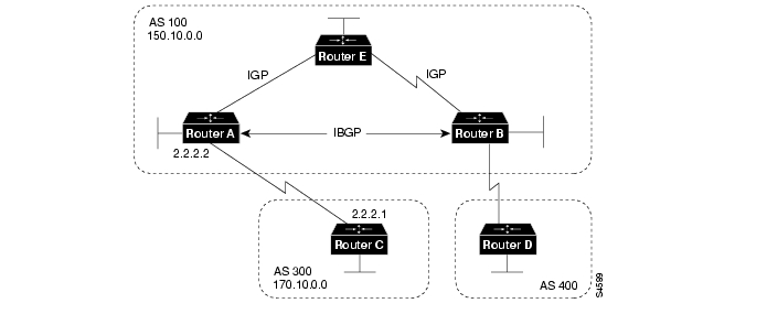
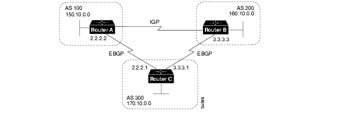
When an AS provides transit service to other ASs and if there are non-BGP routers in the AS, transit traffic might be dropped if the intermediate non-BGP routers have not learned routes for that traffic via an IGP. The BGP synchronization rule states that if an AS provides transit service to another AS, BGP should not advertise a route until all of the routers within the AS have learned about the route via an IGP. The topology shown in demonstrates the synchronization rule.
Figure 12-6 Synchronization
In , Router C sends updates about network 170.10.0.0 to Router A. Routers A and B are running IBGP, so Router B receives updates about network 170.10.0.0 via IBGP. If Router B wants to reach network 170.10.0.0, it sends traffic to Router E. If Router A does not redistribute network 170.10.0.0 into an IGP, Router E has no way of knowing that network 170.10.0.0 exists and will drop the packets.
If Router B advertises to AS 400 that it can reach 170.10.0.0 before Router E learns about the network via IGP, traffic coming from Router D to Router B with a destination of 170.10.0.0 will flow to Router E and be dropped.
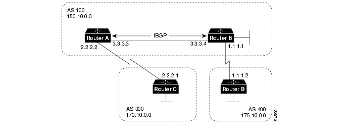
This situation is handled by the synchronization rule of BGP, which states that if an AS (such as AS 100 in ) passes traffic from one AS to another AS, BGP does not advertise a route before all routers within the AS (in this case, AS 100) have learned about the route via an IGP. In this case, Router B waits to hear about network 170.10.0.0 via an IGP before it sends an update to Router D. In some cases, you might want to disable synchronization. Disabling synchronization allows BGP to converge more quickly, but it might result in dropped transit packets.
You can disable synchronization if one of the following conditions is true:
•
•
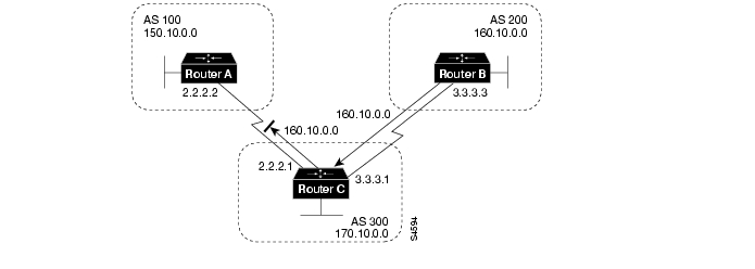
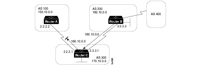
shows a topology in which it is desirable to disable synchronization.
Figure 12-7 Disabled Synchronization
The following commands configure Routers A, B, and C:
!Router Anetwork 150.10.0.0neighbor 3.3.3.4 remote-as 100neighbor 2.2.2.1 remote-as 300no synchronization!Router Brouter bgp 100network 150.10.0.0neighbor 1.1.1.2 remote-as 400neighbor 3.3.3.3 remote-as 100no synchronization!Router Drouter bgp 400neighbor 1.1.1.1 remote-as 100network 175.10.0.0The no synchronization router configuration command causes Router B to put 170.10.0.0 in its IP routing table and advertise it to Router D without learning network 170.10.0.0 via an IGP.
BGP and Route Maps
Route maps are used with BGP to control and modify routing information and to define the conditions by which routes are redistributed between routing domains. The format of a route map is as follows:
route-map map-tag [[permit | deny] | [sequence-number]]The map tag is a name that identifies the route map, and the sequence number indicates the position that an instance of the route map is to have in relation to other instances of the same route map. (Instances are ordered sequentially.)
For example, you might use the following commands to define a route map named MYMAP:
route-map MYMAP permit 10! First set of conditions goes here.route-map MYMAP permit 20! Second set of conditions goes here.When BGP applies MYMAP to routing updates, it applies the lowest instance first (in this case, instance 10). If the first set of conditions is not met, the second instance is applied, and so on, until either a set of conditions has been met, or there are no more sets of conditions to apply.
The match and set route map configuration commands are used to define the condition portion of a route map. The match command specifies a criteria that must be matched, and the set command specifies an action that is to be taken if the routing update meets the condition defined by the match command.
Following is an example of a simple route map:
route-map MYMAP permit 10match ip address 1.1.1.1set metric 5When an update matches IP address 1.1.1.1, BGP sets the metric for the update to 5, sends the update (because of the permit keyword), and breaks out of the list of route-map instances.
When an update does not meet the criteria of an instance, BGP applies the next instance of the route map to the update, and so on, until an action is taken, or there are no more route map instances to apply. If the update does not meet any criteria, the update is not redistributed or controlled.
When an update meets the match criteria, and the route map specifies the deny keyword, BGP breaks out of the list of instances, and the update is not redistributed or controlled.
Note
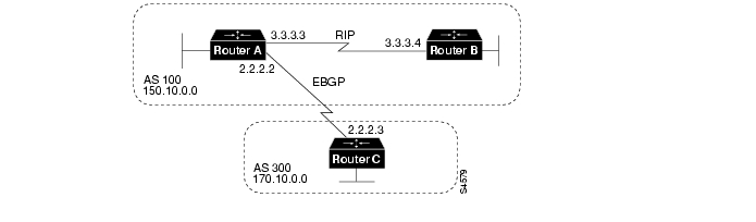
shows a topology that demonstrates the use of route maps.
Figure 12-8 Route Map Example
In , Routers A and B run RIP with each other, and Routers A and C run BGP with each other. If you want Router A to redistribute routes from 170.10.0.0 with a metric of 2 and to redistribute all other routes with a metric of 5, use the following commands for Router A:
!Router Arouter ripnetwork 3.0.0.0network 2.0.0.0network 150.10.0.0passive-interface serial 0redistribute bgp 100 route-map SETMETRIC!router bgp 100neighbor 2.2.2.3 remote-as 300network 150.10.0.0!route-map SETMETRIC permit 10match ip-address 1set metric 2!route-map SETMETRIC permit 20set metric 5!access-list 1 permit 170.10.0.0 0.0.255.255When a route matches the IP address 170.10.0.0, it is redistributed with a metric of 2. When a route does not match the IP address 170.10.0.0, its metric is set to 5, and the route is redistributed.
Assume that on Router C you want to set to 300 the community attribute of outgoing updates for network 170.10.0.0. The following commands apply a route map to outgoing updates on Router C:
!Router Crouter bgp 300network 170.10.0.0neighbor 2.2.2.2 remote-as 100neighbor 2.2.2.2 route-map SETCOMMUNITY out!route-map SETCOMMUNITY permit 10match ip address 1set community 300!access-list 1 permit 0.0.0.0 255.255.255.255Access list 1 denies any update for network 170.10.0.0 and permits updates for any other network.
Advertising Networks
A network that resides within an AS is said to originate from that network. To inform other ASs about its networks, the AS advertises them. BGP provides three ways for an AS to advertise the networks that it originates:
•
•
Note
This section uses the topology shown in to demonstrate how networks that originate from an AS can be advertised.
Figure 12-9 Network Advertisement Example 1
Redistributing Static Routes
One way to advertise that a network or a subnet originates from an AS is to redistribute static routes into BGP. The only difference between advertising a static route and advertising a dynamic route is that when you redistribute a static route, BGP sets the origin attribute of updates for the route to Incomplete. (For a discussion of other values that can be assigned to the origin attribute, see the section " Origin Attribute," later in this chapter.)
To configure Router C in to originate network 175.220.0.0 into BGP, use these commands:
!Router Crouter bgp 200neighbor 1.1.1.1 remote-as 300redistribute static!ip route 175.220.0.0 0.0.255.255 null 0The redistribute router configuration command and the static keyword cause all static routes to be redistributed into BGP.
The ip route global configuration command establishes a static route for network 175.220.0.0. In theory, the specification of the null 0 interface would cause a packet destined for network 175.220.0.0 to be discarded. In practice, there will be a more specific match for the packet than 175.220.0.0, and the router will send it out the appropriate interface. Redistributing a static route is the best way to advertise a supernet because it prevents the route from flapping.
Note
Redistributing Dynamic Routes
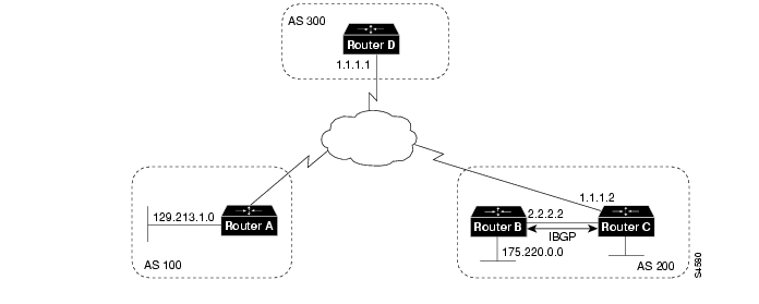
Another way to advertise networks is to redistribute dynamic routes. Typically, you redistribute IGP routes (such as Enhanced IGRP, IGRP, IS-IS, OSPF, and RIP routes) into BGP. Some of your IGP routes might have been learned from BGP, so you need to use access lists to prevent the redistribution of routes back into BGP.
Assume that in Routers B and C are running IBGP, that Router C is learning 129.213.1.0 via BGP, and that Router B is redistributing 129.213.1.0 back into Enhanced IGRP. The following commands configure Router C:
!Router Crouter eigrp 10network 175.220.0.0redistribute bgp 200redistributed connecteddefault-metric 1000 100 250 100 1500!router bgp 200neighbor 1.1.1.1 remote-as 300neighbor 2.2.2.2 remote-as 200neighbor 1.1.1.1 distribute-list 1 outredistribute eigrp 10!access-list 1 permit 175.220.0.0 0.0.255.255The redistribute router configuration command with the eigrp keyword redistributes Enhanced IGRP routes for process ID 10 into BGP. (Normally, distributing BGP into IGP should be avoided because too many routes would be injected into the AS.) The neighbor distribute-list router configuration command applies access list 1 to outgoing advertisements to the neighbor whose IP address is 1.1.1.1 (that is, Router D). Access list 1 specifies that network 175.220.0.0 is to be advertised. All other networks, such as network 129.213.1.0, are implicitly prevented from being advertised. The access list prevents network 129.213.1.0 from being injected back into BGP as if it originated from AS 200, and allows BGP to advertise network 175.220.0.0 as originating from AS 200.
Note
Using the network Command
Another way to advertise networks is to use the network router configuration command. When used with BGP, the network command specifies the networks that the AS originates. (By way of contrast, when used with an IGP such as RIP, the network command identifies the interfaces on which the IGP is to run.) The network command works for networks that the router learns dynamically or that are configured as static routes. The origin attribute of routes that are injected into BGP by means of the network command is set to IGP.
The following commands configure Router C to advertise network 175.220.0.0:
!Router Crouter bgp 200neighbor 1.1.1.1 remote-as 300network 175.220.0.0The network router configuration command causes Router C to generate an entry in the BGP routing table for network 175.220.0.0.
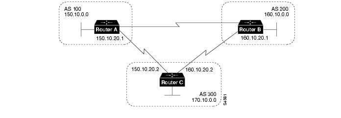
shows another topology that demonstrates the effects of the network command.
Figure 12-10 Network Advertisement Example 2
The following configurations use the network command to configure the routers shown in :
!Router Arouter bgp 100neighbor 150.10.20.2 remote-as 300network 150.10.0.0!Router Brouter bgp 200neighbor 160.10.20.2 remote-as 300network 160.10.0.0!Router Crouter bgp 300neighbor 150.10.20.1 remote-as 100neighbor 160.10.20.1 remote-as 200network 170.10.0.0To ensure a loop-free interdomain topology, BGP does not accept updates that originated from its own AS. For example, in , if Router A generates an update for network 150.10.0.0 with the origin set to AS 100 and sends it to Router C, Router C will pass the update to Router B with the origin still set to AS 100. Router B will send the update (with the origin still set to AS 100) to Router A, which will recognize that the update originated from its own AS and will ignore it.
BGP Decision Algorithm
When a BGP speaker receives updates from multiple ASs that describe different paths to the same destination, it must choose the single best path for reaching that destination. Once chosen, BGP propagates the best path to its neighbors. The decision is based on the value of attributes (such as next hop, administrative weights, local preference, the origin of the route, and path length) that the update contains and other BGP-configurable factors. This section describes the following attributes and factors that BGP uses in the decision-making process:
•
AS_path Attribute
Whenever an update passes through an AS, BGP prepends its AS number to the update. The AS_path attribute is the list of AS numbers that an update has traversed in order to reach a destination. An AS-SET is a mathematical set of all the ASs that have been traversed.
Consider the network shown in .
Figure 12-11 AS_path Attribute
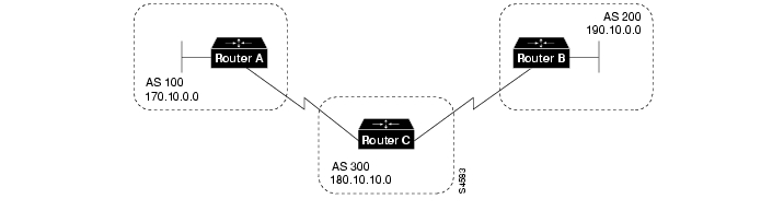
In , Router B advertises network 190.10.0.0 in AS 200 with an AS_path of 200. When the update for 190.10.0.0 traverses AS 300, Router C prepends its own AS number to it, so when the update reaches Router A, two AS numbers have been attached to it: 200 and then 300. That is, the AS_path attribute for reaching network 190.10.0.0 from Router A is 300, 200. Likewise, the AS_path attribute for reaching network 170.10.0.0 from Router B is 300, 100.
Origin Attribute
The origin attribute provides information about the origin of the route. The origin of a route can be one of three values:
•
•
•
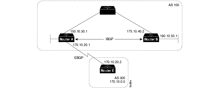
shows a network that demonstrates the value of the origin attribute.
Figure 12-12 Origin Attribute
The following commands configure the routers shown in :
!Router Arouter bgp 100neighbor 190.10.50.1 remote-as 100neighbor 170.10.20.2 remote-as 300network 150.10.0.0redistribute static!ip route 190.10.0.0 255.255.0.0 null 0!Router Brouter bgp 100neighbor 150.10.30.1 remote-as 100network 190.10.50.0!Router Erouter bgp 300neighbor 170.10.20.1 remote-as 100network 170.10.0.0Given these configurations, the following is true:
•
•
•
•
Next Hop Attribute
The BGP next hop attribute is the IP address of the next hop that is going to be used to reach a certain destination.
For EBGP, the next hop is usually the IP address of the neighbor specified by the neighbor remote-as router configuration command. (The exception is when the next hop is on a multiaccess media, in which case, the next hop could be the IP address of the router in the same subnet.) Consider the network shown in .
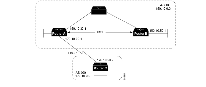
Figure 12-13 Next Hop Attribute
In , Router C advertises network 170.10.0.0 to Router A with a next hop attribute of 170.10.20.2, and Router A advertises network 150.10.0.0 to Router C with a next hop attribute of 170.10.20.1.
BGP specifies that the next hop of EBGP-learned routes should be carried without modification into IBGP. Because of that rule, Router A advertises 170.10.0.0 to its IBGP peer (Router B) with a next hop attribute of 170.10.20.2. As a result, according to Router B, the next hop to reach 170.10.0.0 is 170.10.20.2, instead of 150.10.30.1. For that reason, the configuration must ensure that Router B can reach 170.10.20.2 via an IGP. Otherwise, Router B will drop packets destined for 170.10.0.0 because the next hop address is inaccessible.
For example, if Router B runs IGRP, Router A should run IGRP on network 170.10.0.0. You might want to make IGRP passive on the link to Router C so that only BGP updates are exchanged.
The following commands configure the routers shown in :
!Router Arouter bgp 100neighbor 170.10.20.2 remote-as 300neighbor 150.10.50.1 remote-as 100network 150.10.0.0!Router Brouter bgp 100neighbor 150.10.30.1 remote-as 100!Router Crouter bgp 300neighbor 170.10.20.1 remote-as 100network 170.10.0.0
Note
Next Hop Attribute and Multiaccess Media
BGP might set the value of the next hop attribute differently on multiaccess media, such as Ethernet. Consider the network shown in .
Figure 12-14 Next Hop Attribute and Multiaccess Media
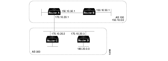
In , Routers C and D in AS 300 are running OSPF. Router C is running BGP with Router A. Router C can reach network 180.20.0.0 via 170.10.20.3. When Router C sends a BGP update to Router A regarding 180.20.0.0, it sets the next hop attribute to 170.10.20.3, instead of its own IP address (170.10.20.2). This is because Routers A, B, and C are in the same subnet, and it makes more sense for Router A to use Router D as the next hop rather than taking an extra hop via Router C.
Next Hop Attribute and Nonbroadcast Media Access
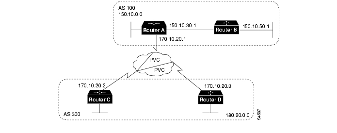
In , three networks are connected by a nonbroadcast media access (NBMA) cloud, such as Frame Relay.
Figure 12-15 Next Hop Attribute and Nonbroadcast Media Access
If Routers A, C, and D, use a common media such as Frame Relay (or any NBMA cloud), Router C advertises 180.20.0.0 to Router A with a next hop of 170.10.20.3, just as it would do if the common media were Ethernet. The problem is that Router A does not have a direct permanent virtual connection (PVC) to Router D and cannot reach the next hop, so routing will fail. To remedy this situation, use the neighbor next-hop-self router configuration command, as shown in the following configuration for Router C:
!Router Crouter bgp 300neighbor 170.10.20.1 remote-as 100neighbor 170.10.20.1 next-hop-selfThe neighbor next-hop-self command causes Router C to advertise 180.20.0.0 with the next hop attribute set to 170.10.20.2.
Weight Attribute
The weight attribute is a special Cisco attribute that is used in the path selection process when there is more than one route to the same destination. The weight attribute is local to the router on which it is assigned, and it is not propagated in routing updates. By default, the weight attribute is 32768 for paths that the router originates and zero for other paths. Routes with a higher weight are preferred when there are multiple routes to the same destination.
Consider the network shown in .
Figure 12-16 Weight Example
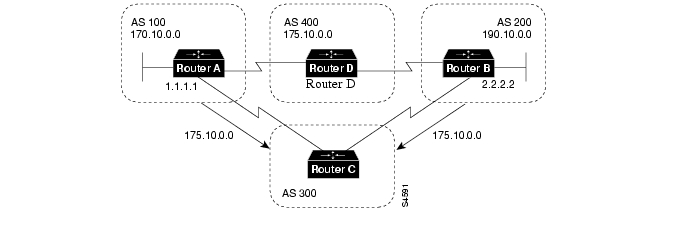
In , Routers A and B learn about network 175.10.0.0 from AS 400, and each propagates the update to Router C. Router C has two routes for reaching 175.10.0.0 and has to decide which route to use. If, on Router C, you set the weight of the updates coming in from Router A to be higher than the updates coming in from Router B, Router C will use Router A as the next hop to reach network 175.10.0.0.
There are three ways to set the weight for updates coming in from Router A:
•
•
•
Using an Access List to Set the Weight Attribute
The following commands on Router C use access lists and the value of the AS_path attribute to assign a weight to route updates:
!Router Crouter bgp 300neighbor 1.1.1.1 remote-as 100neighbor 1.1.1.1 filter-list 5 weight 2000neighbor 2.2.2.2 remote-as 200neighbor 2.2.2.2 filter-list 6 weight 1000!ip as-path access-list 5 permit ^100$ip as-path access-list 6 permit ^200$In this example, 2000 is assigned to the weight attribute of updates from the neighbor at IP address 1.1.1.1 that are permitted by access list 5. Access list 5 permits updates whose AS_path attribute starts with 100 (as specified by ^) and ends with 100 (as specified by $). (The ^ and $ symbols are used to form regular expressions. For a complete explanation of regular expressions, see the appendix on regular expressions in the Cisco Internetwork Operating System (Cisco IOS) software configuration guides and command references.
This example also assigns 1000 to the weight attribute of updates from the neighbor at IP address 2.2.2.2 that are permitted by access list 6. Access list 6 permits updates whose AS_path attribute starts with 200 and ends with 200.
In effect, this configuration assigns 2000 to the weight attribute of all route updates received from AS 100 and assigns 1000 to the weight attribute of all route updates from AS 200.
Using a Route Map to Set the Weight Attribute
The following commands on Router C use a route map to assign a weight to route updates:
!Router Crouter bgp 300neighbor 1.1.1.1 remote-as 100neighbor 1.1.1.1 route-map SETWEIGHTIN inneighbor 2.2.2.2 remote-as 200neighbor 2.2.2.2 route-map SETWEIGHTIN in!ip as-path access-list 5 permit ^100$!route-map SETWEIGHTIN permit 10match as-path 5set weight 2000route-map SETWEIGHTIN permit 20set weight 1000This first instance of the setweightin route map assigns 2000 to any route update from AS 100, and the second instance of the setweightin route map assigns 1000 to route updates from any other AS.
Using the neighbor weight Command to Set the Weight Attribute
The following configuration for Router C uses the neighbor weight router configuration command:
!Router Crouter bgp 300neighbor 1.1.1.1 remote-as 100neighbor 1.1.1.1 weight 2000neighbor 2.2.2.2 remote-as 200neighbor 2.2.2.2 weight 1000This configuration sets the weight of all route updates from AS 100 to 2000, and the weight of all route updates coming from AS 200 to 1000. The higher weight assigned to route updates from AS 100 causes Router C to send traffic through Router A.
Local Preference Attribute
When there are multiple paths to the same destination, the local preference attribute indicates the preferred path. The path with the higher preference is preferred (the default value of the local preference attribute is 100). Unlike the weight attribute, which is only relevant to the local router, the local preference attribute is part of the routing update and is exchanged among routers in the same AS.
The network shown in demonstrates the local preference attribute.
Figure 12-17 Local Preference
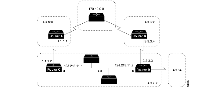
In , AS 256 receives route updates for network 170.10.0.0 from AS 100 and AS 300. There are two ways to set local preference:
•
•
Using the bgp default local-preference Command
The following configurations use the bgp default local-preference router configuration command to set the local preference attribute on Routers C and D:
!Router Crouter bgp 256neighbor 1.1.1.1 remote-as 100neighbor 128.213.11.2 remote-as 256bgp default local-preference 150!Router Drouter bgp 256neighbor 3.3.3.4 remote-as 300neighbor 128.213.11.1 remote-as 256bgp default local-preference 200The configuration for Router C causes it to set the local preference of all updates from AS 300
to 150, and the configuration for Router D causes it to set the local preference for all updates from AS 100 to 200. Because local preference is exchanged within the AS, both Routers C and D determine that updates regarding network 170.10.0.0 have a higher local preference when they come from AS 300 than when they come from AS 100. As a result, all traffic in AS 256 destined for network 170.10.0.0 is sent to Router D as the exit point.Using a Route Map to Set Local Preference
Route maps provide more flexibility than the bgp default local-preference router configuration command. When the bgp default local-preference command is used on Router D in , the local preference attribute of all updates received by Router D will be set to 200, including updates from AS 34.
The following configuration uses a route map to set the local preference attribute on Router D specifically for updates regarding AS 300:
!Router Drouter bgp 256neighbor 3.3.3.4 remote-as 300route-map SETLOCALIN inneighbor 128.213.11.1 remote-as 256!ip as-path 7 permit ^300$route-map SETLOCALIN permit 10match as-path 7set local-preference 200!route-map SETLOCALIN permit 20With this configuration, the local preference attribute of any update coming from AS 300 is set
to 200. Instance 20 of the SETLOCALIN route map accepts all other routes.Multi-Exit Discriminator Attribute
The multi-exit discriminator (MED) attribute is a hint to external neighbors about the preferred path into an AS when there are multiple entry points into the AS. A lower MED value is preferred over a higher MED value. The default value of the MED attribute is 0.
Note
Unlike local preference, the MED attribute is exchanged between ASs, but a MED attribute that comes into an AS does not leave the AS. When an update enters the AS with a certain MED value, that value is used for decision making within the AS. When BGP sends that update to another AS, the MED is reset to 0.
Unless otherwise specified, the router compares MED attributes for paths from external neighbors that are in the same AS. If you want MED attributes from neighbors in other ASs to be compared, you must configure the bgp always-compare-med command.
The network shown in demonstrates the use of the MED attribute.
Figure 12-18 MED Example
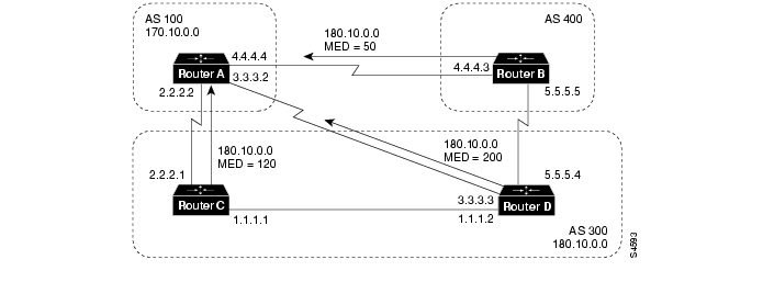
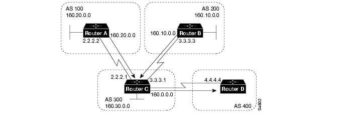
In , AS 100 receives updates regarding network 180.10.0.0 from Routers B, C, and D. Routers C and D are in AS 300, and Router B is in AS 400.
The following commands configure Routers A, B, C, and D:
!Router Arouter bgp 100neighbor 2.2.2.1 remote-as 300neighbor 3.3.3.3 remote-as 300neighbor 4.4.4.3 remote-as 400!Router Brouter bgp 400neighbor 4.4.4.4 remote-as 100neighbor 4.4.4.4 route-map SETMEDOUT outneighbor 5.5.5.4 remote-as 300!route-map SETMEDOUT permit 10set metric 50!Router Crouter bgp 300neighbor 2.2.2.2 remote-as 100neighbor 2.2.2.2 route-map SETMEDOUT outneighbor 5.5.5.5 remote-as 400neighbor 1.1.1.2 remote-as 300!route-map SETMEDOUT permit 10set metric 120!Router Drouter bgp 300neighbor 3.3.3.2 remote-as 100neighbor 3.3.3.2 route map SETMEDOUT outneighbor 1.1.1.1 remote-as 300route-map SETMEDOUT permit 10set metric 200By default, BGP compares the MED attributes of routes coming from neighbors in the same external AS (such as AS 300 in ). Router A can only compare the MED attribute coming from Router C (120) to the MED attribute coming from Router D (200) even though the update coming from Router B has the lowest MED value.
Router A will choose Router C as the best path for reaching network 180.10.0.0. To force Router A to include updates for network 180.10.0.0 from Router B in the comparison, use the bgp always-compare-med router configuration command, as in the following modified configuration for Router A:
!Router Arouter bgp 100neighbor 2.2.2.1 remote-as 300neighbor 3.3.3.3 remote-as 300neighbor 4.4.4.3 remote-as 400bgp always-compare-medRouter A will choose Router B as the best next hop for reaching network 180.10.0.0 (assuming that all other attributes are the same).
You can also set the MED attribute when you configure the redistribution of routes into BGP. For example, on Router B you can inject the static route into BGP with a MED of 50 as in the following configuration:
!Router Brouter bgp 400redistribute staticdefault-metric 50!ip route 160.10.0.0 255.255.0.0 null 0The preceding configuration causes Router B to send out updates for 160.10.0.0 with a MED attribute of 50.
Community Attribute
The community attribute provides a way of grouping destinations (called communities) to which routing decisions (such as acceptance, preference, and redistribution) can be applied.
Route maps are used to set the community attribute. A few predefined communities are listed in .
Table 12-1 Predefined Communities
The following route maps set the value of the community attribute:
route-map COMMUNITYMAPmatch ip address 1set community no-advertise!route-map SETCOMMUNITYmatch as-path 1set community 200 additiveIf you specify the additive keyword, the specified community value is added to the existing value of the community attribute. Otherwise, the specified community value replaces any community value that was set previously.
To send the community attribute to a neighbor, you must use the neighbor send-community router configuration command, as in the following example:
router bgp 100neighbor 3.3.3.3 remote-as 300neighbor 3.3.3.3 send-communityneighbor 3.3.3.3 route-map setcommunity outFor examples of how the community attribute is used to filter updates, see the section " Community Filtering," later in this chapter.
Summary of the BGP Path Selection Process
BGP selects only one path as the best path. When the path is selected, BGP puts the selected path in its routing table and propagates the path to its neighbors. BGP uses the following criteria, in the order presented, to select a path for a destination:
1
2
3
4
5
6
7
8
9
10
Controlling the Flow of BGP Updates
This section describes techniques for controlling the flow of BGP updates. The techniques include the following:
•
Administrative Distance
Normally, a route could be learned via more than one protocol. Administrative distance is used to discriminate between routes learned from more than one protocol. The route with the lowest administrative distance is installed in the IP routing table. By default, BGP uses the administrative distances shown in .
Table 12-2 BGP Default Distances
External
20
Applied to routes learned from EBGP
Internal
200
Applied to routes learned from IBGP
Local
200
Applied to routes originated by the router
Note
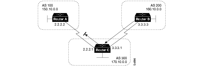
Usually when a route is learned via EBGP, it is installed in the IP routing table because of its
distance (20). Sometimes, however, two ASs have an IGP-learned backdoor route and an EBGP-learned route. Their policy might be to use the IGP-learned path as the preferred path and to use the EBGP-learned path when the IGP path is down. The network in shows this situation.Figure 12-19 Back Door Example
In , Routers A and C are running EBGP, as are Routers B and C. Routers A and B are running an IGP (such as RIP, IGRP, Enhanced IGRP, or OSPF). The default distances for RIP, IGRP, Enhanced IGRP, and OSPF are 120, 100, 90, and 110, respectively. All of these default distances are higher than the default distance of EBGP (which is 20). Usually, the route with the lowest distance is preferred.
Router A receives updates about 160.10.0.0 from two routing protocols: EBGP and an IGP. Because the default distance for EBGP is lower than the default distance of the IGP, Router A will choose the EBGP-learned route from Router C. If you want Router A to learn about 160.10.0.0 from Router B (IGP), you could use one of the following techniques:
•
•
•
To establish a BGP back door, use the network backdoor router configuration command.
The following commands configure Router A in :
!Router Arouter eigrp 10network 150.10.0.0router bgp 100neighbor 2.2.2.1 remote-as 300network 160.10.0.0 backdoorWith the network backdoor command, Router A treats the EBGP-learned route as local and installs it in the IP routing table with a distance of 200. The network is also learned via Enhanced IGRP (with a distance of 90), so the Enhanced IGRP route is successfully installed in the IP routing table and is used to forward traffic. If the Enhanced IGRP-learned route goes down, the EBGP-learned route will be installed in the IP routing table and used to forward traffic.
Note
BGP Filtering
You can control the sending and receiving of updates by using the following filtering methods:
Each method can be used to achieve the same result—the choice of method depends on the specific network configuration.
Prefix Filtering
To restrict the routing information that the router learns or advertises, you can filter based on routing updates to or from a particular neighbor. The filter consists of an access list that is applied to updates to or from a neighbor.
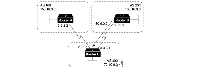
The network shown in demonstrates the usefulness of prefix filtering.
Figure 12-20 Route Filtering
In , Router B is originating network 160.10.0.0 and sending it to Router C. If you want to prevent Router C from propagating updates for network 160.10.0.0 to AS 100, you can apply an access list to filter those updates when Router C exchanges updates with Router A, as demonstrated by the following configuration for Router C:
!Router Crouter bgp 300network 170.10.0.0neighbor 3.3.3.3 remote-as 200neighbor 2.2.2.2 remote-as 100neighbor 2.2.2.2 distribute-list 1 out!access-list 1 deny 160.10.0.0 0.0.255.255access-list 1 permit 0.0.0.0 255.255.255.255In the preceding configuration, the combination of the neighbor distribute-list router configuration command and access list 1 prevents Router C from propagating routes for network 160.10.0.0 when it sends routing updates to neighbor 2.2.2.2 (Router A).
Using access lists to filter supernets is a bit trickier. Assume, for example, that Router B in has different subnets of 160.10.x.x, and you want to advertise 160.0.0.0/8 only. The following access list would permit 160.0.0.0/8, 160.0.0.0/9, and so on:
access-list 1 permit 160.0.0.0 0.255.255.255To restrict the update to 160.0.0.0/8 only, you have to use an extended access list, such as the following:
access-list 101 permit ip 160.0.0.0 0.255.255.255 255.0.0.0 0.0.0.0AS_path Filtering
You can specify an access list on both incoming and outgoing updates based on the value of the AS_path attribute.
The network shown in demonstrates the usefulness of AS_path filters.
Figure 12-21 AS_path Filtering
!Router Cneighbor 3.3.3.3 remote-as 200neighbor 2.2.2.2 remote-as 100neighbor 2.2.2.2 filter-list 1 out!ip as-path access-list 1 deny ^200$ip as-path access-list 1 permit .*In this example, access list 1 denies any update whose AS_path attribute starts with 200 (as specified by ^) and ends with 200 (as specified by $). Because Router B sends updates about 160.10.0.0 whose AS_path attributes start with 200 and end with 200, such updates will match the access list and will be denied. By specifying that the update must also end with 200, the access list permits updates from AS 400 (whose AS_path attribute is 200, 400). If the access list specified ^200 as the regular expression, updates from AS 400 would be denied.
In the second access-list statement, the period (.) symbol means any character, and the asterisk (*) symbol means a repetition of that character. Together, .* matches any value of the AS_path attribute, which in effect permits any update that has not been denied by the previous access-list statement.
If you want to verify that your regular expressions work as intended, use the following EXEC command:
show ip bgp regexp regular-expressionThe router displays all of the paths that match the specified regular expression.
Route Map Filtering
The neighbor route-map router configuration command can be used to apply a route map to incoming and outgoing routes.
Note
The network shown in demonstrates using route maps to filter BGP updates.
Figure 12-22 BGP Route Map Filtering
Assume that in , you want Router C to learn about networks that are local to AS 200 only. (That is, you do not want Router C to learn about AS 100, AS 400, or AS 600 from AS 200.) Also, on those routes that Router C accepts from AS 200, you want the weight attribute to be set
to 20. The following configuration for Router C accomplishes this goal:!Router Crouter bgp 300network 170.10.0.0neighbor 3.3.3.3 remote-as 200neighbor 3.3.3.3 route-map STAMP in!route-map STAMP permit 10match as-path 1set weight 20!ip as-path access-list 1 permit ^200$In the preceding configuration, access list 1 permits any update whose AS_path attribute begins
with 200 and ends with 200 (that is, access list 1 permits updates that originate in AS 200). The weight attribute of the permitted updates is set to 20. All other updates are denied and dropped.Assume that in , you want Router C to do the following:
•
•
•
The following configuration for Router C accomplishes this goal:
!Router Crouter bgp 300network 170.10.0.0neighbor 3.3.3.3 remote-as 200neighbor 3.3.3.3 route-map STAMP inroute-map STAMP permit 10match as-path 1set weight 20!route-map STAMP permit 20match as-path 2!route-map STAMP permit 30set weight 10!ip as-path access-list 1 permit ^200$ip as-path access-list 2 deny _400_In the preceding configuration, access list 1 permits any update whose AS_path attribute begins
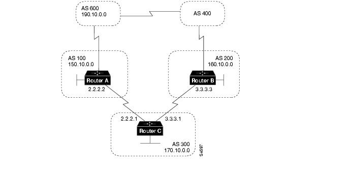
with 200 and ends with 200 (that is, access list 1 permits updates that originate in AS 200). The weight attribute of the permitted updates is set to 20. Access list 2 denies updates whose AS_path attribute contains 400. All other updates will have a weight of 10 (by means of instance 30 of the STAMP route map) and will be permitted.Suppose that in Router C advertises its own network (170.10.0.0) to AS 100 and AS 200. When updates about network 170.10.0.0 arrive in AS 600, the routers in AS 600 will have network reachability information via two routes: via AS 100 with an AS_path attribute of (100, 300) and via AS 400 with an AS_path attribute of (400, 200, 300). Assuming that the values of all other attributes are the same, the routers in AS 600 will pick the shortest AS_path attribute: the route through AS 100.
If you want to use the configuration of Router C to influence the choice of paths in AS 600, you can do so by prepending extra AS numbers to the AS_path attribute for routes that Router C advertises to AS 100. A common practice is to repeat the AS number, as in the following configuration:
!Router Crouter bgp 300network 170.10.0.0neighbor 2.2.2.2 remote-as 100neighbor 2.2.2.2 route-map SETPATH out!route-map SETPATH permit 10set as-path prepend 300 300The set as-path route map configuration command with the prepend keyword causes Router C to prepend 300 twice to the value of the AS_path attribute before it sends updates to the neighbor at IP address 2.2.2.2 (Router A). As a result, the AS_path attribute of updates for network 170.10.0.0 that AS 600 receives via AS 100 will be 100, 300, 300, 300, which is longer than the value of the AS_path attribute of updates for network 170.10.0.0 that AS 600 receives via AS 400 (400, 200, 300). AS 600 will choose (400, 200, 300) as the better path.
Community Filtering
The network shown in demonstrates the usefulness of community filters.
Figure 12-23 Community Filtering
Assume that you do not want Router C to propagate routes learned from Router B to Router A. You can do this by setting the community attribute on updates that Router B sends to Router C, as in the following configuration for Router B:
!Router Brouter bgp 200network 160.10.0.0neighbor 3.3.3.1 remote-as 300neighbor 3.3.3.1 send-communityneighbor 3.3.3.1 route-map SETCOMMUNITY out!route-map SETCOMMUNITY permit 10match ip address 1set community no-export!route-map SETCOMMUNITY permit 20!access list 1 permit 0.0.0.0 255.255.255.255For routes that are sent to the neighbor at IP address 3.3.3.1 (Router C), Router B applies the route map named setcommunity. The setcommunity route map sets the community attribute of any update (by means of access list 1) destined for 3.3.3.1 to no-export. The neighbor send-community router configuration command is required to include the community attribute in updates sent to the neighbor at IP address 3.3.3.1.
When Router C receives the updates from Router B, it does not propagate them to Router A because the value of the community attribute is no-export.
Another way to filter updates based on the value of the community attribute is to use the ip community-list global configuration command. Assume that Router B has been configured as follows:
!Router Brouter bgp 200network 160.10.0.0neighbor 3.3.3.1 remote-as 300neighbor 3.3.3.1 send-communityneighbor 3.3.3.1 route-map SETCOMMUNITY out!route-map SETCOMMUNITY permit 10match ip address 2set community 100 200 additiveroute-map SETCOMMUNITY permit 20!access list 2 permit 0.0.0.0 255.255.255.255In the preceding configuration, Router B adds 100 and 200 to the community value of any update destined for the neighbor at IP address 3.3.3.1. To configure Router C to use the ip community-list global configuration command to set the value of the weight attribute based on whether the community attribute contains 100 or 200, use the following configuration:
!Router Crouter bgp 300neighbor 3.3.3.3 remote-as 200neighbor 3.3.3.3 route-map check-community in!route-map check-community permit 10match community 1set weight 20!route-map check-community permit 20match community 2 exactset weight 10!route-map check-community permit 30match community 3!ip community-list 1 permit 100ip community-list 2 permit 200ip community-list 3 permit internetIn the preceding configuration, any route that has 100 in its community attribute matches community list 1 and has its weight set to 20. Any route whose community attribute is only 200 (by virtue of the exact keyword) matches community list 2 and has its weight set to 10. In the last community list (list 3) the use of the internet keyword permits all other updates without changing the value of an attribute. (The internet keyword specifies all routes because all routes are members of the internet community.)
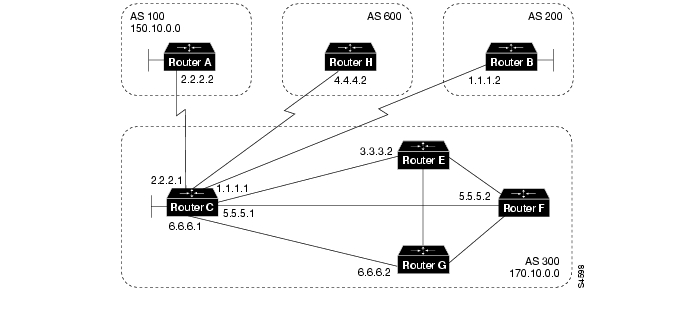
BGP Peer Groups
A BGP peer group is a group of BGP neighbors that share the same update policies. Update policies are usually set by route maps, distribution lists, and filter lists. Instead of defining the same policies for each individual neighbor, you define a peer group name and assign policies to the peer group.
Members of a peer group inherit all of the configuration options of the peer group. Peer group members can also be configured to override configuration options if the options do not affect outgoing updates. That is, you can only override options that are set for incoming updates.
The use of BGP peer groups is demonstrated by the network shown in .
Figure 12-24 BGP Peer Groups
The following commands configure a BGP peer group named internalmap on Router C and apply it to the other routers in AS 300:
!Router Crouter bgp 300neighbor INTERNALMAP peer-groupneighbor INTERNALMAP remote-as 300neighbor INTERNALMAP route-map INTERNAL outneighbor INTERNALMAP filter-list 1 outneighbor INTERNALMAP filter-list 2 inneighbor 5.5.5.2 peer-group INTERNALMAPneighbor 6.6.6.2 peer-group INTERNALMAPneighbor 3.3.3.2 peer-group INTERNALMAPneighbor 3.3.3.2 filter-list 3 inThe preceding configuration defines the following policies for the internalmap peer group:
•
•
•
The configuration applies the peer group to all internal neighbors—Routers E, F, and G. The configuration also defines a filter list for incoming updates from the neighbor at IP address 3.3.3.2 (Router E). This filter list can only be used to override options that affect incoming updates.
The following commands configure a BGP peer group named externalmap on Router C and apply it to routers in AS 100, 200, and 600:
!Router Crouter bgp 300neighbor EXTERNALMAP peer-groupneighbor EXTERNALMAP route-map SETMEDneighbor EXTERNALMAP filter-list 1 outneighbor EXTERNALMAP filter-list 2 inneighbor 2.2.2.2 remote-as 100neighbor 2.2.2.2 peer-group EXTERNALMAPneighbor 4.4.4.2 remote-as 600neighbor 4.4.4.2 peer-group EXTERNALMAPneighbor 1.1.1.2 remote-as 200neighbor 1.1.1.2 peer-group EXTERNALMAPneighbor 1.1.1.2 filter-list 3 inIn the preceding configuration, the neighbor remote-as router configuration commands are placed outside of the neighbor peer-group router configuration commands because different external ASs have to be defined. Also note that this configuration defines filter list 3, which can be used to override configuration options for incoming updates from the neighbor at IP address 1.1.1.2 (Router B).
CIDR and Aggregate Addresses
BGP4 supports classless interdomain routing (CIDR), which is a major improvement over BGP3. (CIDR is also known as supernetting.) CIDR is a new way of looking at IP addresses that eliminates the concept of classes (Class A, Class B, and so on). For example, network 192.213.0.0, which is an illegal Class C network number, is a legal supernet when it is represented in CIDR notation as 192.213.0.0/16. The /16 indicates that the subnet mask consists of 16 bits (counting from the left). Therefore, 192.213.0.0/16 is similar to 192.213.0.0 255.255.0.0.
CIDR makes it easy to aggregate routes. Aggregation is the process of combining several different routes in such a way that a single route can be advertised, which minimizes the size of routing tables.
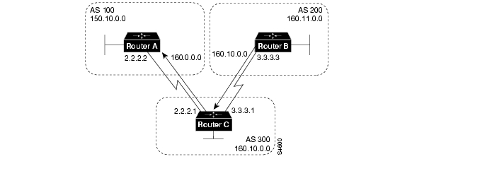
Consider the network shown in .
Figure 12-25 Aggregation
In , Router B in AS 200 is originating network 160.11.0.0 and advertising it to Router C in AS 300. To configure Router C to propagate the aggregate address 160.0.0.0 to Router A, use the following commands:
!Router Crouter bgp 300neighbor 3.3.3.3 remote-as 200neighbor 2.2.2.2 remote-as 100network 160.10.0.0aggregate-address 160.0.0.0 255.0.0.0The aggregate-address router configuration command advertises the prefix route (in this case, 160.0.0.0/8) and all of the more specific routes.
Note
If you want Router C to propagate the prefix route only, and you do not want it to propagate a more specific route, use the following command:
aggregate-address 160.0.0.0 255.0.0.0 summary-onlyThis command propagates the prefix (160.0.0.0/8) and suppresses any more specific routes that the router may have in its BGP routing table.
Note
If you want to suppress specific routes when aggregating routes, you can define a route map and apply it to the aggregate. If, for example, you want Router C in to aggregate 160.0.0.0 and suppress the specific route 160.20.0.0, but propagate route 160.10.0.0, use the following commands:
!Router Crouter bgp 300neighbor 3.3.3.3 remote-as 200neighbor 2.2.2.2 remote-as 100network 160.10.0.0aggregate-address 160.0.0.0 255.0.0.0 suppress-map CHECK!route-map CHECK permit 10match ip address 1!access-list 1 deny 160.20.0.0 0.0.255.255access-list 1 permit 0.0.0.0 255.255.255.255If you want the router to set the value of an attribute when it propagates the aggregate route, use an attribute map, as demonstrated by the following commands:
route-map SETORIGIN permit 10set origin igp!aggregate-address 160.0.0.0 255.0.0.0 attribute-map SETORIGINAggregation and Static Routes
The network shown in demonstrates how static routes can be used to generate aggregates.
Figure 12-26 CIDR Aggregation Example
In , you want Router B to advertise the prefix 160.0.0.0 and suppress all of the more specific routes.
The following configuration for Router B redistributes a static aggregate route into BGP:
!Router Brouter bgp 200neighbor 3.3.3.1 remote-as 300redistribute static!ip route 160.0.0.0 255.0.0.0 null 0As a result of this configuration, Router B advertises the aggregate with an origin attribute whose value is Incomplete.
Using the network router command instead of the redistribute command, as in the following configuration, has the same effect as the preceding configuration except that the origin attribute of updates for network 160.0.0.0 will be set to IGP instead of Incomplete.
!Router Brouter bgp 200network 160.0.0.0 mask 255.0.0.0neighbor 3.3.3.1 remote-as 300!ip route 160.0.0.0 255.0.0.0 null 0
Note
Aggregation and AS-SET
When aggregates are generated from more specific routes, the AS_path attributes of the more specific routes are combined to form a set called the AS-SET. This set is useful for preventing routing information loops.
The network shown in demonstrates the use of AS-SET when aggregating addresses.
Figure 12-27 CIDR Aggregation Example with AS-SET
In , Router C is receiving updates about network 160.20.0.0 from Router A and is receiving updates about network 160.10.0.0 from Router B. If Router C aggregates network 160.0.0.0/8 and sends updates for it to Router D, the AS_path attribute of those updates will indicate that AS 300 is the origin of network 160.0.0.0. If Router D has another route to AS 100, the updates from AS 300 may cause a routing loop. To prevent this problem, use the aggregate-address router configuration command with the as-set keyword, as in the following configuration for Router C:
!Router Cneighbor 3.3.3.3 remote-as 200neighbor 2.2.2.2 remote-as 100neighbor 4.4.4.4 remote-as 400aggregate-address 160.0.0.0 255.0.0.0 as-setThe as-set keyword causes Router C to generate updates for network 160.0.0.0/8 that include information indicating that network 160.0.0.0 belongs to a set (in this case, the set of 100 and 200).
Confederations
A confederation is a technique for reducing the IBGP mesh inside the AS. Consider the network shown in .
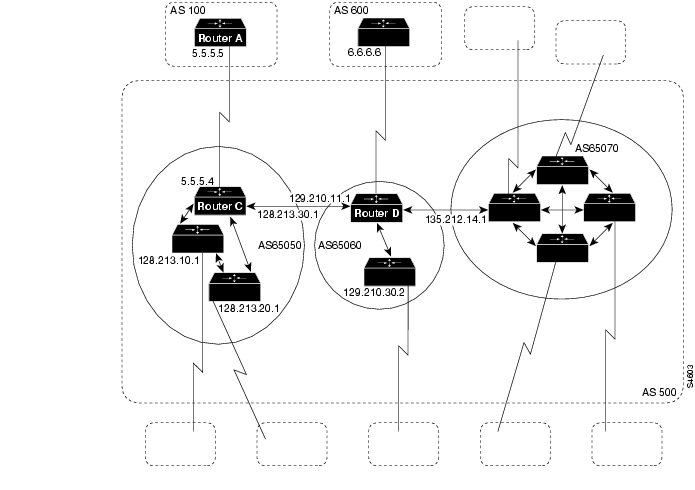
Figure 12-28 Confederations
In , AS 500 consists of nine BGP speakers (although there might be other routers that are not configured for BGP). Without confederations, BGP would require that the routers in AS 500 be fully meshed. That is, each router would need to run IBGP with each of the other eight routers, and each router would need to connect to an external AS and run EBGP, for a total of nine peers for each router.
Confederations reduce the number of peers within the AS, as shown in . You use confederations to divide the AS into multiple mini-ASs and assign the mini-ASs to a confederation. Each mini-AS is fully meshed, and IBGP is run among its members. Each mini-AS has a connection to the other mini-ASs within the confederation. Even though the mini-ASs have EBGP peers to ASs within the confederation, they exchange routing updates as if they were using IBGP—that is, the next hop, MED, and local preference information is preserved. To the outside world, the confederation looks like a single AS.
The following commands configure Router C:
!Router Crouter bgp 65050bgp confederation identifier 500bgp confederation peers 65060 65070neighbor 128.213.10.1 remote-as 65050neighbor 128.213.20.1 remote-as 65050neighbor 128.210.11.1 remote-as 65060neighbor 135.212.14.1 remote-as 65070neighbor 5.5.5.5 remote-as 100The router bgp global configuration command specifies that Router C belongs to AS 50.
The bgp confederation identifier router configuration command specifies that Router C belongs to confederation 500.
The first two neighbor remote-as router configuration commands establish IBGP connections to the other two routers within AS 65050. The second two neighbor remote-as commands establish BGP connections with confederation peers 65060 and 65070. The last neighbor remote-as command establishes an EBGP connection with external AS 100.
The following commands configure Router D:
!Router Drouter bgp 65060bgp confederation identifier 500bgp confederation peers 65050 65070neighbor 129.210.30.2 remote-as 65060neighbor 128.213.30.1 remote-as 65050neighbor 135.212.14.1 remote-as 65070neighbor 6.6.6.6 remote-as 600The router bgp global configuration command specifies that Router D belongs to AS 65060.
The bgp confederation identifier router configuration command specifies that Router D belongs to confederation 500.
The first neighbor remote-as router configuration command establishes an IBGP connection to the other router within AS 65060. The second two neighbor remote-as commands establish BGP connections with confederation peers 65050 and 65070. The last neighbor remote-as command establishes an EBGP connection with AS 600.
The following commands configure Router A:
!Router Arouter bgp 100neighbor 5.5.5.4 remote-as 500The neighbor remote-as command establishes an EBGP connection with Router C. Router A is unaware of AS 65050, AS 65060, or AS 65070. Router A only has knowledge of AS 500.
Route Reflectors
Route reflectors are another solution for the explosion of IBGP peering within an AS. As described earlier in the section " Synchronization," a BGP speaker does not advertise a route learned from another IBGP speaker to a third IBGP speaker. Route reflectors ease this limitation and allow a router to advertise (reflect) IBGP-learned routes to other IBGP speakers, thereby reducing the number of IBGP peers within an AS.
The network shown in demonstrates how route reflectors work.
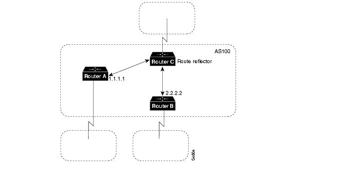
Figure 12-29 Simple Route Reflector Example
Without a route reflector, the network shown in would require a full IBGP mesh (that is, Router A would have to be a peer of Router B). If Router C is configured as a route reflector, IBGP peering between Routers A and B is not required because Router C will reflect updates from Router A to Router B and from Router B to Router A. To configure Router C as a route reflector, use the following commands:
!Router Crouter bgp 100neighbor 1.1.1.1 remote-as 100neighbor 1.1.1.1 route-reflector-clientneighbor 2.2.2.2 remote-as 100neighbor 2.2.2.2 route-reflector-clientThe router whose configuration includes neighbor route-reflector-client router configuration commands is the route reflector. The routers identified by the neighbor route-reflector-client commands are clients of the route reflector. When considered as a whole, the route reflector and its clients are called a cluster. Other IBGP peers of the route reflector that are not clients are called nonclients.
An AS can have more than one route reflector. When an AS has more than one route reflector, each route reflector treats other route reflectors as normal IBGP speakers. There can be more than one route reflector in a cluster, and there can be more than one cluster in an AS.
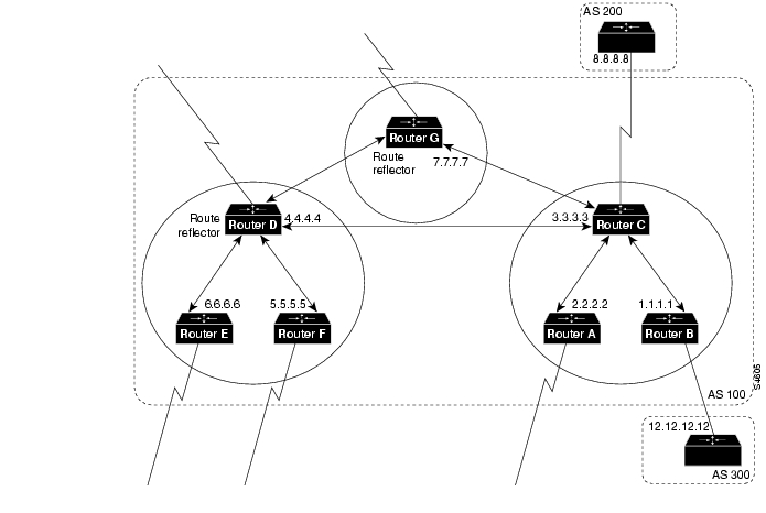
In the advanced configuration shown in , the AS is divided into multiple clusters, with each cluster having one route reflector. Each route reflector is configured as a nonclient peer of each other route reflector in a fully meshed topology.
Note
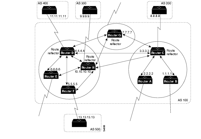
Figure 12-30 Advanced Route Reflectors Example
In , Routers A, B, and C form a cluster, and Router C is the route reflector. Routers D, E, and F form a second cluster, of which Router D is the route reflector. Router G forms a third cluster. Note that Routers C, D, and G are fully meshed and that the routers within a cluster are not fully meshed.
When a route reflector in receives an update, it takes the following actions, depending on the type of peer that sent the update:
•
•
•
The following configurations establish the route reflectors in AS 100:
!Router Crouter bgp 100neighbor 1.1.1.1 remote-as 100neighbor 1.1.1.1 route-reflector-clientneighbor 2.2.2.2 remote-as 100neighbor 2.2.2.2 route-reflector-clientneighbor 7.7.7.7 remote-as 100neighbor 4.4.4.4 remote-as 100neighbor 8.8.8.8 remote-as 200!Router Brouter bgp 100neighbor 3.3.3.3 remote-as 100neighbor 12.12.12.12 remote-as 300!Router Drouter bgp 100neighbor 5.5.5.5 remote-as 100neighbor 5.5.5.5 route-reflector-clientneighbor 6.6.6.6 remote-as 100neighbor 6.6.6.6 route-reflector-clientneighbor 3.3.3.3 remote-as 100neighbor 7.7.7.7 remote-as 100If a set clause is used to modify an attribute, a routing loop may occur when the IBGP-learned routes are reflected. BGP automatically prevents the set clause of outgoing route maps from affecting routes reflected to IBGP peers. Another automatic restriction concerns the neighbor next-hop-self router configuration command. Because the next hop of reflected routes should not be changed, the neighbor next-hop-self command only affects the next hop of EBGP-learned routes when used with route reflectors.
Two techniques prevent routing loops in route reflector configurations:
Using an Originator ID
The originator ID is a 4-byte BGP attribute that is created by the route reflector. This attribute carries the router ID of the originator of the route in the local AS. If, because of poor configuration, the update comes back to the originator, the originator ignores it.
Using a Cluster List
Usually a cluster has a single route reflector, in which case, the cluster is identified by the router ID of the route reflector. To increase redundancy and avoid single points of failure, a cluster might have more than one route reflector. When a cluster has more than one route reflector, all of the route reflectors in the cluster need to be configured with a 4-byte cluster ID. The cluster ID allows route reflectors to recognize updates from other route reflectors in the same cluster.
A cluster list is a sequence of cluster IDs that an update has traversed. When a route reflector sends a route from its clients to nonclients outside of the cluster, it appends the local cluster ID to the cluster list. If the route reflector receives an update whose cluster list contains the local cluster ID, the update is ignored.
In , Routers D, E, F, and H belong to the same cluster; Routers D and H are route reflectors for the same cluster. Note that Routers D and H maintain a fully meshed peering relationship with the other route reflectors in AS 100 (that is, with Routers C and G). If Router D goes down, Router H is prepared to take its place.
Figure 12-31 Route Reflectors and Cluster Lists
The following commands configure Routers C, D, F, and H:
!Router Crouter bgp 100neighbor 1.1.1.1 remote-as 100neighbor 1.1.1.1 route-reflector-clientneighbor 2.2.2.2 remote-as 100neighbor 2.2.2.2 route-reflector-clientneighbor 4.4.4.4 remote-as 100neighbor 7.7.7.7 remote-as 100neighbor 10.10.10.10 remote-as 100neighbor 8.8.8.8 remote-as 200!Router Dneighbor 10.10.10.10 remote-as 100neighbor 5.5.5.5 remote-as 100neighbor 5.5.5.5 route-reflector-clientneighbor 6.6.6.6 remote-as 100neighbor 6.6.6.6 route-reflector-clientneighbor 3.3.3.3 remote-as 100neighbor 7.7.7.7 remote-as 100neighbor 11.11.11.11 remote-as 400bgp cluster-id 10!Router Frouter bgp 100neighbor 10.10.10.10 remote-as 100neighbor 4.4.4.4 remote-as 100neighbor 13.13.13.13 remote-as 500!Router Hrouter bgp 100neighbor 4.4.4.4 remote-as 100neighbor 5.5.5.5 remote-as 100neighbor 5.5.5.5 route-reflector-clientneighbor 6.6.6.6 remote-as 100neighbor 6.6.6.6 route-reflector-clientneighbor 7.7.7.7 remote-as 100neighbor 3.3.3.3 remote-as 100neighbor 9.9.9.9 remote-as 300bgp cluster-id 10The configurations for Routers D and H include the bgp cluster-id router configuration command, which sets the cluster ID to 10. The configuration for Router C does not include the bgp cluster-id command because Router C is the only route reflector in its cluster.
Route Reflectors and Conventional BGP Speakers
It is normal for an AS in which route reflectors are configured to have BGP speakers that do not support route reflection. Such routers are known as conventional BGP speakers.
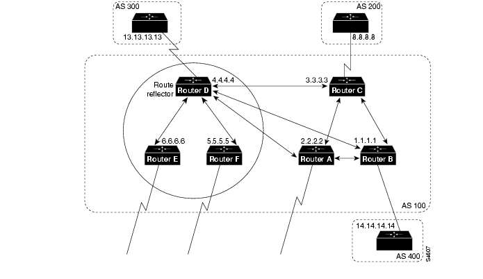
In , Routers D, E, and F form a route reflector cluster, and Routers A, B, and C are conventional BGP speakers.
Figure 12-32 Route Reflectors and Conventional BGP Speakers
In , each conventional BGP speaker is peered with the route reflector (Router D), and Routers A, B, and C are peered among each other.
The following commands configure Routers C and D:
!Router Crouter bgp 100neighbor 4.4.4.4 remote-as 100neighbor 2.2.2.2 remote-as 100neighbor 1.1.1.1 remote-as 100neighbor 8.8.8.8 remote-as 200!Router Drouter bgp 100neighbor 6.6.6.6 remote-as 100neighbor 6.6.6.6 route-reflector-clientneighbor 5.5.5.5 remote-as 100neighbor 5.5.5.5 route-reflector-clientneighbor 3.3.3.3 remote-as 100neighbor 2.2.2.2 remote-as 100neighbor 1.1.1.1 remote-as 100neighbor 13.13.13.13 remote-as 300When it is time to make the conventional BGP speakers members of a cluster, Router C can be configured to be the route reflector, and Routers A and B can be its clients.
Route Flap Dampening
Route flap dampening (introduced in Cisco Internetwork Operating System [Cisco IOS] Release 11.0) is a mechanism for minimizing the instability caused by route flapping. The following terms are used to describe route flap dampening:
•
•
•
•
•
•
A route that is flapping receives a penalty of 1000 for each flap. When the accumulated penalty reaches a configurable limit, BGP suppresses advertisement of the route even if the route is up. The accumulated penalty is decremented by the half-life time. When the accumulated penalty is less than the reuse limit, the route is advertised again (if it is still up).
Note
The network shown in demonstrates route flap dampening.
Figure 12-33 Route Flap Dampening
The following commands configure Routers A and B:
!RouterAhostname RouterA!interface serial 0ip address 203.250.15.2 255.255.255.252interface serial 1ip address 192.208.10.6 255.255.255.252!router bgp 100bgp dampeningnetwork 203.250.15.0neighbor 192.208.10.5 remote-as 300!RouterBhostname RouterB!interface loopback 0ip address 192.208.10.174 255.255.255.192!interface serial 0/0ip address 192.208.10.5 255.255.255.252!router bgp 300network 192.208.10.0neighbor 192.208.10.6 remote-as 100Router A is configured for route dampening. Assuming that the EBGP link to Router B is stable, the BGP table on Router A looks like this:
RouterB# show ip bgptable version is 24, local router ID is 203.250.15.2Status codes: s suppressed, d damped, h history, * valid, > best, i - internalOrigin codes: i - IGP, e - EGP, ? - incompleteNetwork Next Hop Metric LocPrf Weight Path*> 192.208.10.0 192.208.10.5 0 0 300 i*> 203.250.15.0 0.0.0.0 0 32768 iTo simulate a route flap, enter this command on Router B:
clear ip bgp 192.208.10.6Now, the BGP table on Router A looks like this:
RouterA# show ip bgptable version is 24, local router ID is 203.250.15.2Status codes: s suppressed, d damped, h history, * valid, > best, i - internalOrigin codes: i - IGP, e - EGP, ? - incompleteNetwork Next Hop Metric LocPrf Weight Pathh 192.208.10.0 192.208.10.5 0 0 300 i*> 203.250.15.0 0.0.0.0 0 32768 iBecause the route for 192.208.10.0. has flapped, the BGP entry for 192.208.10.0 has been withdrawn and put into the history state.
The output of the show ip bgp EXEC command for network 192.208.10.0 is as follows:
RouterA# show ip bgp 192.208.10.0BGP routing table entry for 192.208.10.5 255.255.255.0, version 25Paths: (1 available, no best path)300 (history entry)192.208.10.5 from 192.208.10.5 (192.208.10.174)Origin IGP, metric 0, externalDampinfo: penalty 1000, flapped 1 times in 0:02:03The route has been given a penalty (1000) for flapping but the penalty is still below the suppress limit (default 2000). Because the route is down, it is marked as a history entry. If the route flaps a few more times, the show ip bgp command displays the following:
RouterA# show ip bgptable version is 32, local router ID is 203.250.15.2Status codes: s suppressed, d damped, h history, * valid, > best, i - internalOrigin codes: i - IGP, e - EGP, ? - incompleteNetwork Next Hop Metric LocPrf Weight Path*d 192.208.10.0 192.208.10.5 0 0 300 i*> 203.250.15.0 0.0.0.0 0 32768 iThe output of the show ip bgp command for network 192.208.10.0 is as follows:
RouterA# show ip bgp 192.208.10.0BGP routing table entry for 192.208.10.5 255.255.255.0, version 32Paths: (1 available, no best path)300, (suppressed due to dampening)192.208.10.5 from 192.208.10.5 (192.208.10.174)Origin IGP, metric 0, externalDampinfo: penalty 2615, flapped 3 times in 0:05:18, reuse in 0:27:00The route is up, but because the penalty is greater than the suppress limit, it is suppressed. The route will be reused when the penalty reaches the reuse limit (default 750). The dampening information will be purged when the penalty becomes less than half of the reuse limit (750/2 = 350).
Practical Design Example
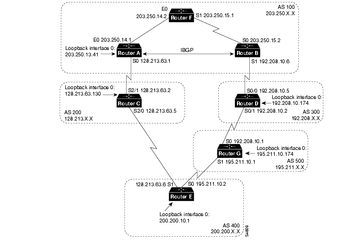
shows a BGP network that demonstrates the types of topologies that are typical among ISPs.
Figure 12-34 Practical Design Example for ISPs
Whenever an AS is connected to two ISPs via EBGP, IBGP should be run within the AS for better control over routes. The following configurations for the routers shown in run OSPF as the IGP and run IBGP between Routers A and B inside AS 100.
The following configurations are preliminary configurations for the routers shown in . These preliminary configurations are incomplete so that BGP troubleshooting techniques can be demonstrated. For the complete configurations, see the section, " Final Configurations," later in this chapter.
!Router Ahostname RouterA!interface loopback 0ip address 203.250.13.41 255.255.255.0!interface ethernet 0ip address 203.250.14.1 255.255.255.0!interface serial 0ip address 128.213.63.1 255.255.255.252!router ospf 10network 203.250.0.0 0.0.255.255 area 0router bgp 100network 203.250.13.0 mask 255.255.255.0network 203.250.14.0 mask 255.255.255.0neighbor 128.213.63.2 remote-as 200neighbor 203.250.15.2 remote-as 100neighbor 203.250.15.2 update-source loopback 0!Router Bhostname RouterB!interface serial 0ip address 203.250.15.2 255.255.255.252!interface serial 1ip address 192.208.10.6 255.255.255.252!router ospf 10network 203.250.0.0 0.0.255.255 area 0!router bgp 100network 203.250.15.0neighbor 192.208.10.5 remote-as 300neighbor 203.250.13.41 remote-as 100!Router Chostname RouterC!interface loopback 0ip address 128.213.63.130 255.255.255.192!interface serial 2/0ip address 128.213.63.5 255.255.255.252!interface serial 2/1ip address 128.213.63.2 255.255.255.252!router bgp 200network 128.213.0.0neighbor 128.213.63.1 remote-as 100neighbor 128.213.63.6 remote-as 400!Router Dhostname RouterD!interface loopback 0ip address 192.208.10.174 255.255.255.192!interface serial 0/0ip address 192.208.10.5 255.255.255.252!interface serial 0/0ip address 192.208.10.5 255.255.255.252!router bgp 300network 192.208.10.0neighbor 192.208.10.1 remote-as 500neighbor 192.208.10.6 remote-as 100!Router Ehostname RouterE!interface loopback 0ip address 200.200.10.1 255.255.255.0interface serial 0ip address 195.211.10.2 255.255.255.252!interface serial 1ip address 128.213.63.6 255.255.255.252!router bgp 400network 200.200.10.0neighbor 128.213.63.5 remote-as 200neighbor 195.211.10.1 remote-as 500!Router Fhostname RouterF!interface ethernet 0ip address 203.250.14.2 255.255.255.0!interface serial 1ip address 203.250.15.1 255.255.255.252!router ospf 10network 203.250.0.0 0.0.255.255 area 0!Router Ghostname RouterG!interface loopback 0ip address 195.211.10.174 255.255.255.192!interface serial 0ip address 192.208.10.1 255.255.255.252!interface serial 1ip address 195.211.10.1 255.255.255.252!router bgp 500network 195.211.10.0neighbor 192.208.10.2 remote-as 300neighbor 195.211.10.2 remote-as 400When you redistribute IGP routes into BGP, you need to control the routes that are injected into BGP. For that reason, it is always better to advertise routes by using the network router configuration command or by redistributing static routes, as shown in the examples in this section. This method also avoids route flaps.
Determining the State of BGP
Assume that in the connection between Routers B and D is down. The following information is displayed when you enter the show ip bgp EXEC command on Router B:
RouterB# show ip bgptable version is 4, local router ID is 203.250.15.2Status codes: s suppressed, d damped, h history, * valid, > best, i - internalOrigin codes: i - IGP, e - EGP, ? - incompleteNetwork Next Hop Metric LocPrf Weight Path*i128.213.0.0 128.213.63.2 0 100 0 200 i*i192.208.10.0 128.213.63.2 100 0 200 400 500 300 i*i195.211.10.0 128.213.63.2 100 0 200 400 500 i*i200.200.10.0 128.213.63.2 100 0 200 400 i*>i203.250.13.0 203.250.13.41 0 100 0 i*>i203.250.14.0 203.250.13.41 0 100 0 i*> 203.250.15.0 0.0.0.0 0 32768 iThe letter i at the beginning of a line means that the entry was learned via an internal BGP peer. The letter i at the end of a line indicates that the path information comes from an IGP. The first entry reads as follows: Network 128.213.0.0 is learned via path 200 and has a next hop of 128.213.63.2. Note that any locally generated entry, such as 203.250.15.0 has a next hop of 0.0.0.0.
The > symbol indicates that BGP has chosen the best route based on the decision steps described in the section " Summary of the BGP Path Selection Process," earlier in this chapter. BGP picks only the one route that it determines to be the best route. It installs this route in the IP routing table and advertises it to other BGP peers. Note the next hop attribute of 128.213.63.2, which is the EBGP next hop carried into IBGP.
Following is the contents of the IP routing table on Router B:
RouterB# show ip routeCodes: C - connected, S - static, I - IGRP, R - RIP, M - mobile, B - BGPD - EIGRP, EX - EIGRP external, O - OSPF, IA - OSPF inter areaE1 - OSPF external type 1, E2 - OSPF external type 2, E - EGPi - IS-IS, L1 - IS-IS level-1, L2 - IS-IS level-2, * - candidate defaultGateway of last resort not set203.250.13.0 255.255.255.255 is subnetted, 1 subnetsO 203.250.13.41 [110/75] via 203.250.15.1, 02:50:45, Serial0203.250.15.0 255.255.255.252 is subnetted, 1 subnetsC 203.250.15.0 is directly connected, Serial0O 203.250.14.0 [110/74] via 203.250.15.1, 02:40:46, Serial0Note than none of the BGP entries appears in the IP routing table. One problem is that the next hop for these entries (128.213.63.2) is unreachable. This is because there is no way to reach that next hop via the IGP (in this case, OSPF). Router B has not learned about 128.213.63.0 via OSPF.
Correcting Next Hop Problems
For the network shown in , the next hop problem can be corrected in one of two ways:
•
•
The following configuration for Router A runs OSPF on interface serial 0 and makes it passive:
!Router Ahostname RouterA!interface loopback 0ip address 203.250.13.41 255.255.255.0!interface ethernet 0ip address 203.250.14.1 255.255.255.0!interface serial 0ip address 128.213.63.1 255.255.255.252!router ospf 10passive-interface serial 0network 203.250.0.0 0.0.255.255 area 0network 128.213.0.0 0.0.255.255 area 0!router bgp 100network 203.250.13.0 mask 255.255.255.0network 203.250.14.0 mask 255.255.255.0neighbor 128.213.63.2 remote-as 200neighbor 203.250.15.2 remote-as 100neighbor 203.250.15.2 update-source loopback 0Now the BGP neighbor table on Router B contains the following routes:
RouterB# show ip bgptable version is 10, local router ID is 203.250.15.2Status codes: s suppressed, d damped, h history, * valid, > best, i - internalOrigin codes: i - IGP, e - EGP, ? - incompleteNetwork Next Hop Metric LocPrf Weight Path*>i128.213.0.0 128.213.63.2 0 100 0 200 i*>i192.208.10.0 128.213.63.2 100 0 200 400 500 300 i*>i195.211.10.0 128.213.63.2 100 0 200 400 500 i*>i200.200.10.0 128.213.63.2 100 0 200 400 i*>i203.250.13.0 203.250.13.41 0 100 0 i*>i203.250.14.0 203.250.13.41 0 100 0 i*> 203.250.15.0 0.0.0.0 0 32768 iNote that a > symbol appears in all of the entries, which means that BGP is satisfied with the next hop address.
Now the IP routing table on Router B contains the following routes:
RouterB# show ip routeCodes: C - connected, S - static, I - IGRP, R - RIP, M - mobile, B - BGPD - EIGRP, EX - EIGRP external, O - OSPF, IA - OSPF inter areaE1 - OSPF external type 1, E2 - OSPF external type 2, E - EGPi - IS-IS, L1 - IS-IS level-1, L2 - IS-IS level-2, * - candidate defaultGateway of last resort not set203.250.13.0 255.255.255.255 is subnetted, 1 subnetsO 203.250.13.41 [110/75] via 203.250.15.1, 00:04:46, Serial0203.250.15.0 255.255.255.252 is subnetted, 1 subnetsC 203.250.15.0 is directly connected, Serial0O 203.250.14.0 [110/74] via 203.250.15.1, 00:04:46, Serial0128.213.0.0 255.255.255.252 is subnetted, 1 subnetsO 1.28.213.63.0 [110/138] via 203.250.15.1, 00:04:47, Serial 0Note that the BGP entries still do not appear in the IP routing table. The only difference is that 128.213.63.0 is now reachable via OSPF. The problem is synchronization: BGP is not synchronized with the IGP, so it does not put the entries in the IP routing table, and it does not send the entries in BGP updates. Router F is not aware of networks 192.208.10.0 or 195.211.10.0 because BGP routes are not redistributed into OSPF yet.
Turning Off Synchronization
If you enter the no synchronization router configuration command on Router B and then examine the IP routing table on Router B, you see the following contents of the IP routing table on Router B:
RouterB# show ip routeCodes: C - connected, S - static, I - IGRP, R - RIP, M - mobile, B - BGPD - EIGRP, EX - EIGRP external, O - OSPF, IA - OSPF inter areaE1 - OSPF external type 1, E2 - OSPF external type 2, E - EGPi - IS-IS, L1 - IS-IS level-1, L2 - IS-IS level-2, * - candidate defaultGateway of last resort not setB 200.200.10.0 [200/0] via 128.213.63.2, 00:01:07B 195.211.10.0 [200/0] via 128.213.63.2, 00:01:07B 192.208.10.0 [200/0] via 128.213.63.2, 00:01:07203.250.13.0 is variably subnetted, 2 subnets, 2 masksO 203.250.13.41 255.255.255.255[110/75] via 203.250.15.1, 00:12:37, Serial0B 203.250.13.0 255.255.255.0 [200/0] via 203.250.13.41, 00:01:08203.250.15.0 255.255.255.252 is subnetted, 1 subnetsC 203.250.15.0 is directly connected, Serial0O 203.250.14.0 [110/74] via 203.250.15.1, 00:12:37, Serial0128.213.0.0 is variably subnetted, 2 subnets, 2 masksB 128.213.0.0 255 255.0.0 [200/0] via 128.213.63.2, 00:01:08O 128.213.63.0 255.255.255.252[110/138] via 203.250.15.1, 00:12:37, Serial0The routing table looks fine, but there is no way to reach those networks because Router F in the middle does not know how to reach them, as shown by the following output of the show ip route EXEC command on Router F:
RouterF# show ip routeCodes: C - connected, S - static, I - IGRP, R - RIP, M - mobile, B - BGPD - EIGRP, EX - EIGRP external, O - OSPF, IA - OSPF inter areaE1 - OSPF external type 1, E2 - OSPF external type 2, E - EGPi - IS-IS, L1 - IS-IS level-1, L2 - IS-IS level-2, * - candidate defaultGateway of last resort is not set203.250.13.0 255.255.255.255 is subnetted, 1 subnetsO 203.250.13.41 [110/11] via 203.250.14.1, 00:14:15, EthernetO203.250.15.0 255.255.255.252 is subnetted, 1 subnetsC 203.250.15.0 is directly connected, SeriallC 203.250.14.0 is directly connected, EthernetO128.213.0.0 255.255.255.252 is subnetted, 1 subnetsO 128.213.63.0 [110/74] via 203.250 14 1, 00:14:15, EthernetOIf packets to the BGP network are forwarded to Router F, they will be dropped, so turning off synchronization does not resolve this particular problem. OSPF still needs to be redistributed into BGP on Router A so that Router F learns about BGP routes.
Redistributing OSPF
The following configuration for Router A has been modified to redistribute OSPF (the new command is in bold):
!Router Ahostname RouterA!interface loopback 0ip address 203.250.13.41 255.255.255.0interface ethernet 0ip address 203.250.14.1 255.255.255.0!interface serial 0ip address 128.213.63.1 255.255.255.252!router ospf 10redistribute bgp 100 metric 2000 subnetspassive-interface serial 0network 203.250.0.0 0.0.255.255 area 0network 128.213.0.0 0.0.255.255 area 0!router bgp 100network 203.250.0.0 mask 255.255.0.0neighbor 128.213.63.2 remote-as 200neighbor 203.250.15.2 remote-as 100neighbor 203.250.15.2 update-source loopback 0Now the routing table looks as follows:
RouterB# show ip routeCodes: C - connected, S - static, I - IGRP, R - RIP, M - mobile, B - BGPD - EIGRP, EX - EIGRP external, O - OSPF, IA - OSPF inter areaE1 - OSPF external type 1, E2 - OSPF external type 2, E - EGPi - IS-IS, L1 - IS-IS level-1, L2 - IS-IS level-2, * - candidate defaultGateway of last resort not setO E2 200.200.10.0 [110/2000] via 203.250.15.1, 00:00:14, Serial0O E2 195.211.10.0 [110/2000] via 203.250.15.1, 00:00:14, Serial0O E2 192.208.10.0 [110/2000] via 203.250.15.1, 00:00:14, Serial0203.250.13.0 is variably subnetted, 2 subnets, 2 masksO 203.250.13.41 255.255.255.255[110/75] via 203.250.15.1, 00:00:15, Serial0O E2 203.250.13.0 255.255.255.0[110/2000] via 203.250.15.1, 00:00:15, Serial0203.250.15.0 255.255.255.252 is subnetted, 2 subnetsC 203.250.15.8 is directly connected, LoopbacklC 203.250.15.0 is directly connected, Serial0O 203.250.14.0 [110/74] via 203.250.15.1, 00:00:15, Serial0128.213.0.0 is variably subnetted, 2 subnets, 2 masksO E2 128.213.0.0 255.255.0.0 [110/2000] via 203.250.15.1, 00:00:l5,Serial0O 128.213.63.0 255.255.255.252[110/138] via 203.250.15.1, 00:00:16, Serial0The BGP entries have disappeared because OSPF has a better distance (110) than IBGP (200).
Turning off synchronization on Router A will cause Router A to advertise network 203.250.15.0. This step is required because Router A will not synchronize with OSPF because of mask differences. For the same reason, synchronization should also be turned off on Router B so that it can advertise network 203.250.13.0.
In addition, OSPF should be enabled on interface serial 1 on Router B and made passive so that Router A learns about next hop 192.208.10.5 via an IGP.
The modified configurations for Routers A and B are as follows. (New commands are in bold.)
!Router Ahostname RouterA!interface loopback 0ip address 203.250.13.41 255.255.255.0!interface ethernet 0ip address 203.250.14.1 255.255.255.0!interface serial 0ip address 128.213.63.1 255.255.255.252!router ospf 10redistribute bgp 100 metric 2000 subnetspassive-interface serial 0network 203.250.0.0 0.0.255.255 area 0network 128.213.0.0 0.0.255.255 area 0!router bgp 100no synchronizationnetwork 203.250.13.0 mask 255.255.255.0network 203.250.14.0 mask 255.255.255.0neighbor 128.213.63.2 remote-as 200neighbor 203.250.15.2 remote-as 100neighbor 203.250.15.2 update-source loopback 0!Router Bhostname RouterB!interface serial 0ip address 203.250.15.2 255.255.255.252!interface serial 1ip address 192.208.10.6 255.255.255.252!router ospf 10redistribute bgp 100 metric 1000 subnetspassive-interface serial 1network 203.250.0.0 0.0.255.255 area 0network 192.208.0.0 0.0.255.255 area 0!router bgp 100network 203.250.15.0neighbor 192.208.10.5 remote-as 300neighbor 203.250.13.41 remote-as 100Now bring up interface serial 1 on Router B and see what the BGP neighbor table looks like on Router A:
RouterA# show ip bgptable version is 117, local router ID is 203.250.13.41Status codes: s suppressed, d damped, h history, * valid, > best, i - internalOrigin codes: i - IGP, e - EGP, ? - incompleteNetwork Next Hop Metric LocPrf Weight Path*> 128.213.0.0 128.213.63.2 0 100 0 200 i*>i192.208.10.0 192.208.10.5 0 100 0 300 i*>i195.211.10.0 192.208.10.5 100 0 300 500 i* 128.213.63.2 0 200 400 500 i*> 203.250.13.0 0.0.0.0 0 32768 i*> 203.250.14.0 0.0.0.0 0 32768 i*>i203.250.15.0 203.250.15.2 0 100 0 iFollowing is the output of the show ip route EXEC command on Router A:
RouterA# show ip routeCodes: C - connected, S - static, I - IGRP, R - RIP, M - mobile, B - BGPD - EIGRP, EX - EIGRP external, O - OSPF, IA - OSPF inter areaE1 - OSPF external type 1, E2 - OSPF external type 2, E - EGPi - IS-IS, L1 - IS-IS level-1, L2 - IS-IS level-2, * - candidate defaultGateway of last resort not set192.208.10.0 is variably subnetted, 2 subnets, 2 masksO E2 192.208.10.0 255.255.255.0[110/1000] via 203.250.14.2, 00:41:25, Ethernet0O 192.208.10 4 255.255.255.252[110/138] via 203.250.14.2, 00:41:25, Ethernet0C 203.250.13.0 is directly connected, Loopback0203.250.15.0 is variably subnetted, 3 subnets, 3 masksO 203.250.15.10 255.255.255.255[110/75] via 203.250.14.2, 00:41:25, Ethernet0O 203.250.15.0 255.255.255.252[110/74] via 203.250.14.2, 00:41:25, Ethernet0B 203.250.15.0 255.255.255.0 [200/0] via 203.250.15.2, 00:41:25C 203.250.14.0 is directly connected, Ethernet0128.213.0.0 is variably subnetted, 2 subnets, 2 masksB 128.213.0.0 255.255.0.0 [20/0] via 128.213.63.2, 00:41:26C 128.213.63.0 255.255.255.252 is directly connected, Serial0B* 200.200.0.0 255.255.0.0 [20/0] via 128.213.63.2, 00:02:38Following is the output of the show ip bgp EXEC command on Router B:
RouterB# show ip bgptable version is 12, local router ID is 203.250.15.2Status codes: s suppressed, d damped, h history, * valid, > best, i - internalOrigin codes: i - IGP, e - EGP, ? - incompleteNetwork Next Hop Metric LocPrf Weight Path*>i128.213.0.0 128.213.63.2 0 100 0 200 i* 192.208.10.5 0 300 500 400 200 i*> 195.208.10.0 192.208.10.5 0 0 300 i*> 195.211.10.0 192.208.10.5 0 300 500 i*>i200.200.10.0 128.213.63.2 100 0 200 400 i*> 192.208.10.5 0 300 500 400 i*>i203.250.13.0 203.250.13.41 0 100 0 i*>i203.250.14.0 203.250.13.41 0 100 0 i*> 203.250.15.0 0.0.0.0 0 32768 iManaging Asymmetry
There are several ways to design the network for AS 100 to communicate with the ISP networks in AS 200 and AS 300. One way is to have a primary ISP and a backup ISP. AS 100 could learn partial routes from one of the ISPs and default routes to both ISPs. In this example, AS 100 receives partial routes from AS 200 and only local routes from AS 300. Both Routers A and B generate default routes into OSPF, with Router B being the more preferred route because of its lower MED attribute. This allows you to balance outgoing traffic between the two ISPs.
Potential asymmetry might occur if traffic going out from Router A comes back via Router B. This might occur if networks are advertised to both of the ISPs. From outside the AS, the networks are reachable via both of the ISPs and either Router A or B could be used to reach them. You might find out that all incoming traffic to your AS is coming via one single point even though you have multiple points to the internetwork.
One other potential reason for asymmetry is the different advertised path length to reach your AS. One ISP might be closer to a certain destination than another. In this example, traffic from AS 400 destined for AS 100 always comes in via Router A because of the shorter path. You might try to affect that decision by using the set as-path route map configuration command with the prepend keyword to prepend AS numbers to your updates to make the AS_path attribute longer. But, if AS 400 has somehow set its exit point to be via AS 200 based on attributes such as local preference, MED attribute, weight, there is nothing you can do.
Final Configurations
Following is the final configuration for Router A. (New or modified commands are in bold.)
!Router Ahostname RouterA!interface loopback 0ip address 203.250.13.41 255.255.255.0!interface ethernet 0ip address 203.250.14.1 255.255.255.0!interface serial 0ip address 128.213.63.1 255.255.255.252!router ospf 10redistribute bgp 100 metric 2000 subnetspassive-interface serial 0network 203.250.0.0 0.0.255.255 area 0network 128.213.0.0 0.0.255.255 area 0default-information originate metric 2000!router bgp 100no synchronizationneighbor 128.213.63.2 remote-as 200neighbor 128.213.63.2 route-map setlocalpref inneighbor 203.250.15.2 remote-as 100neighbor 203.250.15.2 update-source loopback 0!ip default-network 200.200.0.0!route-map setlocalpref permit 10set local-preference 200The final configuration for Router A sets the local preference for routes coming from AS 200 to 200. The configuration also uses the ip default-network global configuration command to specify network 200.200.0.0 as the candidate default route. The ip default-information originate router configuration command is used to inject the default route inside the OSPF domain. For RIP, network 0.0.0.0 is automatically redistributed into RIP without additional configuration. For IGRP and Enhanced IGRP, default information is injected into the IGP domain after BGP is redistributed. Also, with IGRP and Enhanced IGRP, you can redistribute a static route for 0.0.0.0 into the IGP domain.
Following is the final configuration for Router B. (New or modified commands are in bold.)
!Router Bhostname RouterB!interface serial 0ip address 203.250.15.2 255.255.255.252!interface serial 1ip address 192.208.10.6 255.255.255.252router ospf 10redistribute bgp 100 metric 1000 subnetspassive-interface serial 1network 203.250.0.0 0.0.255.255 area 0network 192.208.0.0 0.0.255.255 area 0default-information originate metric 1000!router bgp 100no synchronizationnetwork 203.250.15.0neighbor 192.208.10.5 remote-as 300neighbor 192.208.10.5 route-map LOCALONLY inneighbor 203.250.13.41 remote-as 100!ip default-network 192.208.10.0ip as-path access-list 1 permit ^300 500$ip as-path access-list 2 permit ^300$!route-map LOCALONLY permit 10match as-path 1set local-preference 300!route-map LOCALONLY permit 20match as-path 2The configuration for Router B sets the local preference for updates coming from AS 300 having an AS_path attribute of 300, 500 to 300, which is higher than the IBGP updates coming in from Router A in AS 100. This way, AS 100 will pick Router B for AS 500's local routes. Any other routes on Router B (if there are any) will be sent internally with a local preference of 100, which is lower than the local preference of 200 coming in from Router A. This arrangement causes Router A to be preferred. Further, because of the length of the AS_path attribute, Router B is used to reach routes local to AS 300.
Note that Router B accepts the local routes of AS 300 and AS 500 only. Any updates whose AS_path attribute does not match are dropped. If you want to advertise the local routes and the neighbor routes (customers of the ISP), you can use ^300_[0-9]* as the regular expression. The following is the output of the show ip bgp EXEC command for regular expression ^300$:
RouterB# show bgp regexp ^300$BGP table version is 14, local router ID is 203.250.15.2Status code: s suppressed, d damped, h history, * valid, > best, i - internalOrigin codes: i - IGP, e - EGP, ? - incompleteNetwork Next Hop Metric LocPrf Weight Path*> 192.208.10.0 192.28.10.5 0 300 0 300Following is the final configuration for Router C. (New and modified commands are in bold.)
!Router Chostname RouterC!interface loopback 0ip address 128.213.63.130 255.255.255.192!interface serial 2/0ip address 128.213.63.5 255.255.255.252!interface serial 2/1ip address 128.213.63.2 255.255.255.252!router bgp 200network 128.213.0.0aggregate-address 128.213.0.0 255.255.0.0 summary-onlyneighbor 128.213.63.1 remote-as 100neighbor 128.213.63.1 distribute-list 1 outneighbor 128.213.63.6 remote-as 400!access-list 1 deny 195.211.0.0 0.0.255.255access-list 1 permit anyThe configuration for Router C aggregates network 128.213.0.0/16 and specifies the routes that are to be injected into AS 100. If the ISP refuses to do this task, you have to filter routes coming into AS 100 on Router A.
Following are the final configurations for Routers D and E. (New or modified commands are in bold.)
!Router Dhostname RouterD!interface loopback 0ip address 192.208.10.174 255.255.255.192!interface serial 0/0ip address 192.208.10.5 255.255.255.252!interface serial 0/1ip address 192.208.10.2 255.255.255.252!router bgp 300network 192.208.10.0neighbor 192.208.10.1 remote-as 500neighbor 192.208.10.6 remote-as 100!Router Ehostname RouterE!interface loopback 0ip address 200.200.10.1 255.255.255.0interface serial 0ip address 195.211.10.2 255.255.255.252!interface serial 1ip address 128.213.63.6 255.255.255.252!router bgp 400network 200.200.10.0aggregate-address 200.200.0.0 255.255.0.0 summary-onlyneighbor 128.213.63.5 remote-as 200neighbor 195.211.10.1 remote-as 500Router E is aggregating network 200.200.0.0/16.
Following are the final configurations for Routers F and G. (New or modified commands are in bold.)
!Router Fhostname RouterF!interface ethernet 0ip address 203.250.14.2 255.255.255.0!interface serial 1ip address 203.250.15.1 255.255.255.252!router ospf 10network 203.250.0.0 0.0.255.255 area 0!Router Ghostname RouterG!interface loopback 0ip address 195.211.10.174 255.255.255.192!interface serial 0ip address 192.208.10.1 255.255.255.252!interface serial 1ip address 195.211.10.1 255.255.255.252!router bgp 500network 195.211.10.0aggregate-address 195.211.0.0 255.255.0.0 summary-onlyneighbor 192.208.10.2 remote-as 300neighbor 192.208.10.2 send-communityneighbor 192.208.10.2 route-map setcommunity outneighbor 195.211.10.2 remote-as 400!access-list 2 permit anyaccess-list 101 permit ip 195.211.0.0 0.0.255.255 255.255.255.0 0.0.0.255!route-map setcommunity permit 10match ip address 101set community no-export!route-map setcommunity permit 20match ip address 2The configuration for Router G demonstrates the use of community filtering by adding the no-export community to more specific Class C routes of 195.211.0.0/16 that are sent to Router D. This way, Router D will not export that route to Router B.
Following is the final content of BGP routing table on Router A:
RouterA# show ip bgptable version is 21, local router ID is 203.250.13.41Status codes: s suppressed, d damped, h history, * valid, > best, i - internalOrigin codes: i - IGP, e - EGP, ? - incompleteNetwork Next Hop Metric LocPrf Weight Path*> 128.213.0.0 128.213.63.2 0 200 0 200 i*>i192.208.10.0 192.208.10.5 0 300 0 300 i*> 200.200.0.0/16 128.213.63.2 200 0 200 400 i*> 203.250.13.0 0.0.0.0 0 32768 i*> 203.250.14.0 0.0.0.0 0 32768 i*>i203.250.15.0 203.250.15.2 0 100 0 iFollowing is the final content of the IP routing table on Router A:
RouterA# show ip routeCodes: C - connected, S - static, I - IGRP, R - RIP, M - mobile, B - BGPD - EIGRP, EX - EIGRP external, O - OSPF, IA - OSPF inter areaE1 - OSPF external type 1, E2 - OSPF external type 2, E - EGPi - IS-IS, L1 - IS-IS level-1, L2 - IS-IS level-2, * - candidate defaultGateway of last resort is 128.213.63.2 to network 200.200.0.0192.208.10.0 is variably subnetted, 2 subnets, 2 masksO E2 192.208.10.0 255.255.255.0[110/1000] via 203.250.14.2, 00:41:25, Ethernet0O 192.208.10.4 255.255.255.252[110/138] via 203.250.14.2, 00:41:25, Ethernet0C 203.250.13.0 is directly connected, Loopback0203.250.15.0 is variably subnetted, 3 subnets, 3 masksO 203.250.15.10 255.255.255.255[110/75] via 203.250.14.2, 00:41:25, Ethernet0O 203.250.15.0 255.255.255.252[110/74] via 203.250.14.2, 00:41:25, Ethernet0B 203.250.15.0 255.255.255.0 [200/0] via 203.250.15.2, 00:41:25C 203.250.14.0 is directly connected, Ethernet0128.213.0.0 is variably subnetted, 2 subnets, 2 masksB 128.213.0.0 255.255.0.0 [20/0] via 128.213.63.2, 00:41:26C 128.213.63.0 255.255.255.252 is directly connected, Serial0B* 200.200.0.0 255.255.0.0 [20/0] via 128.213.63.2, 00:02:38Following is the final content of IP routing table on Router F:
RouterF# show ip routeCodes: C - connected, S - static, I - IGRP, R - RIP, M - mobile, B - BGPD - EIGRP, EX - EIGRP external, O - OSPF, IA - OSPF inter areaE1 - OSPF external type 1, E2 - OSPF external type 2, E - EGPi - IS-IS, L1 - IS-IS level-1, L2 - IS-IS level-2, * - candidate defaultGateway of last resort is 203.250.15.2 to network 0.0.0.0192.208.10.0 is variably subnetted, 2 subnets, 2 masksO E2 192.208.10.0 255.255.255.0[110/1000] via 203.250.15.2, 00:48:50, Serial1O 192.208.10.4 255.255.255.252[110/128] via 203.250.15.2, 01:12:09, Serial1203.250.13.0 is variably subnetted, 2 subnets, 2 masksO 203.250.13.41 255.255.255.255[110/11] via 203.250.14.1, 01:12:09, Ethernet0O E2 203.250.13.0 255.255.255.0[110/2000] via 203.250.14.1, 01:12:09, Ethernet0203.250.15.0 is variably subnetted, 2 subnets, 2 masksO 203.250.15.10 255.255.255.255[110/65] via 203.250.15.2, 01:12:09, Serial1C 203.250.14.0 is directly connected, Ethernet0128.213.0.0 255.255.0.0 is variably subnetted, 2 subnets, 2 masksO E2 128.213.0.0 255.255.0.0[110/2000] via 203.250.14.1, 00:45:01, Ethernet0O E2 200.200.0.0 255.255.0.0 [110/1000] via 203.250.14.1, 00:03:47, Ethernet0O*E2 0.0.0.0 0.0.0.0 [110/1000] via 203.250.15.2, 00:03:33, Serial1Note that on Router F, the routing table indicates that networks local to AS 300, such as 192.208.10.0 are to be reached via Router B. Other known networks, such as 200.200.0.0 are to be reached via Router A. The gateway of last resort is set to Router B. If something happens to the connection between Router B and Router D, the default advertised by Router A will kick in with a MED attribute of 2000.
Following is the final content of BGP routing table on Router B:
RouterB# show ip bgptable version is 14, local router ID is 203.250.15.10Status codes: s suppressed, d damped, h history, * valid, > best, i - internalOrigin codes: i - IGP, e - EGP, ? - incompleteNetwork Next Hop Metric LocPrf Weight Path*>i128.213.0.0 128.213.63.2 0 200 0 200 i*> 192.208.10.0 192.208.10.5 0 300 0 300 i*>i200.200.0.0/16 128.213.63.2 200 0 200 400 i*>i203.250.13.0 203.250.13.41 0 100 0 i*>i203.250.14.0 203.250.13.41 0 100 0 i*> 203.250.15.0 0.0.0.0 0 32768 iFollowing is the final content of the IP routing table on Router B:
RouterF# show ip routeCodes: C - connected, S - static, I - IGRP, R - RIP, M - mobile, B - BGPD - EIGRP, EX - EIGRP external, O - OSPF, IA - OSPF inter areaE1 - OSPF external type 1, E2 - OSPF external type 2, E - EGPi - IS-IS, L1 - IS-IS level-1, L2 - IS-IS level-2, * - candidate defaultGateway of last resort is 203.250.15.2 to network 192.208.10.0* 192.208.10.0 is variably subnetted, 2 subnets, 2 masksB* 192.208.10.0 255.255.255.0 [20/0] via 192.208.10.5, 00:50:46C 192.208.10.4 255.255.255.252 is directly connected, Serial1203.250.13.0 is variably subnetted, 2 subnets, 2 masksO 203.250.13.41 255.255.255.255[110/75] via 203.250.15.1, 01:20:33, Serial0O E2 203.250.13.0 255.255.255.0[110/2000] via 203.250.15.1, 01:15:40, Serial0203.250.15.0 255.255.255.252 is subnetted, 2 subnets, 2 masksO 203.250.15.10 255.255.255.255[110/65] via 203.250.15.2, 01:12:09, Serial1C 203.250.14.0 is directly connected, Ethernet0128.213.0.0 255.255.0.0 is variably subnetted, 2 subnetsC 203.250.15.8 id directly connected, Loopback1C 203.250.15.0 is directly connected, Serial0O 203.250.14.0 [110/74] via 203.250.15.1, 01:20:33, Serial0128.213.0.0 is variably subnetted, 2 subnets, 2 masksO E2 128.213.0.0 255.255.0.0 [110/2000] via 203.250.15.1, 00:46:55, Serial0Summary
The primary function of a BGP system is to exchange network reachability information with other BGP systems. This information is used to construct a graph of AS connectivity from which routing loops are pruned and with which AS-level policy decisions are enforced. BGP provides a number of techniques for controlling the flow of BGP updates, such as route, path, and community filtering. It also provides techniques for consolidating routing information, such as CIDR aggregation, confederations, and route reflectors. BGP is a powerful tool for providing loop-free interdomain routing within and between ASs.
![]()
![]()
![]()
![]()
![]()
![]()
![]()
![]()
Posted: Mon Aug 22 07:54:28 PDT 2005
All contents are
Copyright © 1992--2005 Cisco Systems, Inc. All rights reserved.
Important Notices and Privacy Statement.