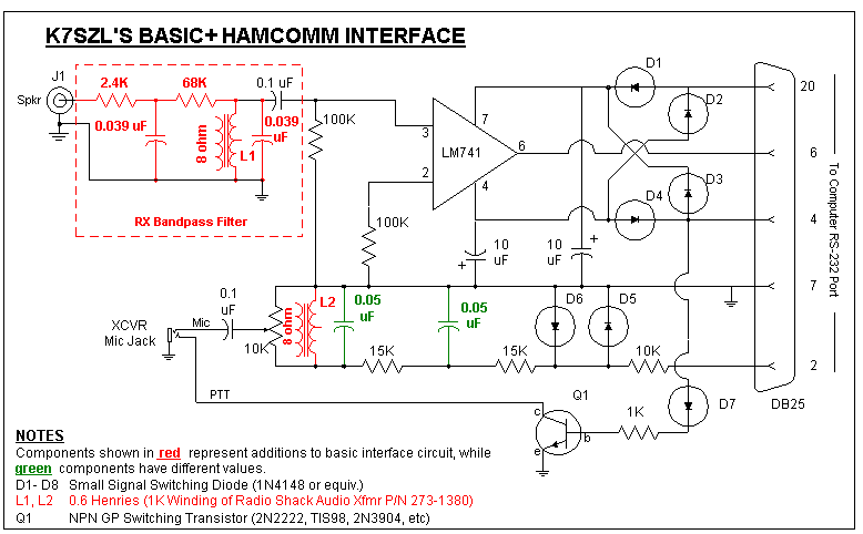
The philosophy underlying HamComm has been to make the digital modes accessible to the widest possible audience, including novices with rudimentary electronic construction skills. This approach can be seen in the simplicity of the basic hardware interface - minimum component count, readily available parts, and only one adjustment. Unfortunately, this simplicity has proven to be a two-edged sword - on one hand, it has allowed hams and short wave listeners throughout the world to successfully construct the interface and begin enjoying the RTTY and AMTOR modes. On the other hand, the basic interface lacks sufficient front-end selectivity to realize the full capabilities inherent in the HamComm software - introduce a little QRM or QRN along with the desired signal, and print quality goes out the window. As a result, many who have tried HamComm have been disappointed in its performance.
Fortunately, it is a simple task to upgrade the basic hardware interface to the "Basic+" configuration. By addiing six readily available passive components with a total cost of under $5, HamComm's weak signal receive performance is noticeably improved. The schematic below shows the basic interface circuit in black, added components in red, and basic circuit components whose values have changed in green. If you are not an experienced builder, you may want to consider getting the basic interface circuit up and running before incorporating the Basic+ enhancements.

The circuit above incorporates two enhancements to the basic HamComm interface:
While the modifications described above have been tested on CW, RTTY, AMTOR, and PACTOR, I have not had the opportunity to try them with other modes such as SSTV, WEFAX, or 300/1200 BPS packet. I suspect that the filter bandwidth will be excessively narrow for these modes.
IMPORTANT
If you implement these filters, don't forget to set the default center frequency in the HC31.CFG file to 1100 Hz.
POSTSCRIPT: Bill, KD7S, built the Basic+ using the recommended components and sent an e-mail describing a problem that he ran into. In his circuit, it seems that the one of the two LC circuits that differentiate the Basic+ from the Basic interface did not resonate at the design frequency of 1100 Hz. He measured the inductance of the Radio Shack transformers he purchased and found that one was 780 mH and the other was 230 mH. It appears that Radio Shack doesn't exercise a great deal of configuration control over their component suppliers - I suspect that they purchase industrial surplus components and production closeouts from a variety of manufacturers based on whatever is cheapest. The fix to this is fairly straightforward, but it does require that you know (by measurement, specification, or inference) the value(s) of the inductors you intend to use. I use a WaveTek DVM which has an inductance measuring function built into it, but if you lack the proper test equipment, you're going to have to get creative. Consider one of the following:
If it turns out that the value of your inductor is different than the 0.7 mH specified in the Basic + circuit, you can calculate the appropriate value of capacitor needed to hit resonance with the following formula:
C = 1/(39.4 * f * f * L)
Where C = required capacitance value in farads
f = desired center frequency in hertz
L = Value of your inductor in Henries
If you have a choice of inductors of similar values, select the one that has the least resistance - this will give you a narrower bandwidth and better performance. One other caution - don't choose a center frequency less than 1100 Hz or so. The third harmonic attentuation of the TX filter is only about 25 dB which is not sufficient to avoid transmitting two or more sets of mark and space frequencies on the air. The Basic + design depends upon the additional attentuation offered by the transceiver IF filter, which is accomplished by making sure that the third harmonic of the AFSK tones fall outside the nominal 2.7 KHz bandwidth of the transceiver filter.