 No. 7 The Poor Old ZL Special
Because the ZL Special is such a mechanically simple and cheap antenna, it has spent its nearly half century of life misunderstood. Rightly understood, it has a place in the 10-10 inventory of antennas. It will not cure the blues on a rainy day or make DX in the absence of sunspots, but it may make a very useful attic or field antenna.
ZL3MH (later ZL2OQ and recently a silent key) brought the antenna to ham attention in 1949, giving credit to W5LHI and W0GZR for basic information on the design. G2BCX, who has developed variations on the design from the earliest days to the present, dubbed it the "ZL Special," and the name stuck.
The basic idea is deceptively simple: take a driven element and a slightly longer reflector and space them between a tenth and an eighth wavelength apart. Next, connect the elements with an eighth wavelength of transmission line (adjusted for velocity factor of the line) with a half twist, and feed the former driven element with ladder line to an antenna tuner. The result is a 135° phased array. In the early 1950s when hams had difficulties building Yagis at home, the antenna seemed to outperform 3-element Yagis and give almost miraculous front-to-back ratios. The claims are almost embarrassing today.
First, the ZL Special, in any form, will have the gain of a 2-element Yagi at best. In fact, most decent designs show about 6.1 dBi forward gain in free space, about the same as the broadband Yagi described in the last column and about 4 dB better than a similar sized and placed dipole.
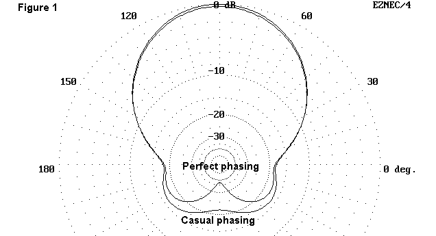
Second, the front-to-back ratio can range from great to mediocre depending upon design care, luck, and Murphy. Figure 1 shows two patterns of the version we shall physically describe below. They are taken over real medium earth at a height of 20' (for reasons we shall also note below). Casual building can achieve the broader pattern, while extensive design and experimental work might approach the "perfect" pattern.
The perfect pattern might not be more especially useful than the casual pattern, since it is so pinched. Any rear QRM just off center line will not feel the effects of the high front-to-back ratio, since it will fall within the off-center lobes. The casual pattern is only slightly worse than the lobes of the perfect pattern. Looking at the entire rear sector of an azimuth pattern is sometimes called analyzing the "front-to- rear" ratio.
The casual pattern is still useful for certain kinds of applications. It provides a better than 15 dB front-to-rear ratio across the entire backside. If the mechanical features of the antenna fit your building needs, then it may pay to try a ZL Special.
Most of ZL3MH's designs used unequal elements. A few years back, W7EL published a Field Day Special version of the antenna using equal length elements. Hence, I tend to call unequal element versions ZL Specials and equal element versions FD Specials. W7EL's antenna is made (like some predecessors) from 300-ohm good quality TV feedline. The general configuration appears in Fig. 2., scaled for 10-meter use.
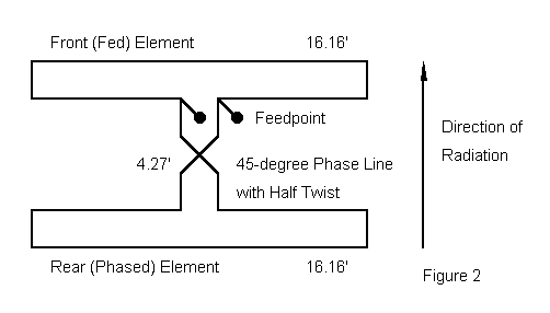
The elements are folded dipoles 16'2" long. The 300-ohm phasing section is 4'3¼" long with a half twist between the front and rear elements. The phase line here is designed to be the same length as the distance between elements, thus producing a taut assembly.
You can feed the antenna in two basic ways. One way is to place capacitors in series with each feedpoint to compensate for some remaining inductive reactance at the feedpoint. Then a 1:1 choke balun links the feedpoint to regular coaxial cable. If finding the right amount of capacity to place at the feedpoint is a bit too much trouble, then feed the antenna with more 300-ohm ribbon brought to an antenna tuner. The feedpoint compensation will have no bearing on the basic properties of the antenna.
Heavy plastic squares with stress-relief slots and small machine screws as tie-point anchors should make easy work of the mechanical connections, front and rear. You can tape the antenna to bamboo and simulate a Yagi, but that is probably not the best use of the antenna. Better applications are as an attic antenna or an antenna strung between trees on Field Day and similar operations. A spacer bar at each end of the antenna and some rope ties will hold the antenna in place. These applications prompted the 20' height patterns, since they rarely permit very high antennas.
W7EL also noted a convenience: he attached half-wavelength sections of twin lead dangling from both the front and rear junctions. One just dangles (without touching the ground) while the other is connected either to the antenna tuner or the coax feedline. Swapping leads reverses the direction of the array. The dangling open-end half-wavelength line acts like a very high impedance, which affects antenna performance very little, if at all. Adjust these lines for the velocity factor of the ribbon cable, about .8 for most common 300-ohm twinlead.
Sounds simple, doesn't it? Mechanically, it is simple, but electronically, things get a little more complex. Some call the ZL Special a 135° phased array because they think of the rear element as 180° minus the 45° twisted phase line out of phase with the front element. This is true with respect to impedance values found at each element. However, it is current magnitude and phase which determine the performance of the array, and the target ballpark for that current is 315° (which is also -45°) out of phase with the front element. The half twist of the phase line is equivalent to twisting the element itself 180° with respect to the front element, with an added 45° phase line between them.
Now let's make it a little more complicated: for any 2-element horizontal antenna, there is an optimum current magnitude and phase angle for the center of the rear element to give the maximum front-to-back ratio. If the elements are about an eighth-wavelength apart, the current magnitude is near the value on the front element and the current phase angle is nearly -45° relative to the front element. But, the antenna element lengths are also part of the overall geometry, and so the exact values for maximum front-to-back ratio are rarely these ideals. If you radically alter the geometry, like bending the elements toward each other at the ends, the natural values (or parasitic values, if you like to think in Yagi terms) change considerably from those found with straight elements at the same spacing.
Finding the exact dimensions for a perfectly phased ZL Special can be daunting and unrewarding, especially since the values also change with the antenna height above ground. (The "perfect" pattern in Fig. 1 required a modeled rear element current of 1.01 times the current on the forward element and a phase angle of -40.8° and those values differ from the free space model values.) ZL1LE has developed a "lumped constant" matching network that permits him to tune his antenna to the deepest rear nulls as he feeds both junction points with half-wavelength feedlines.
However, there is a big difference between a usable antenna and a perfect antenna. Most ZL Special designs will show little loss in gain and at least 15 dB front-to-back ratio up to 5% above or below the optimal current level and up to 8 or 10 degrees off optimal phasing. Hence, even casual ZL Special designs get the job done, even if they are not perfect. That is why most antenna analysts (who are usually perfectionists) tend to hate the ZL Special, while many a poverty-level or teenage ham has learned to love the antenna.
Like the hams of the 50s, I prefer to use an antenna tuner with the ZL Special because I do not have to recompensate the feedpoint every time I move the antenna. And tuning one up to acceptable performance is a matter of adjusting the length of the phasing line, usually making it longer and a bit more saggy than most of the magazine designs show. Twin lead is cheap enough to experiment with almost endlessly--or at least until the sunspots return.
If your needs fit the mechanics of this antenna, try one. If you love it, you
will love it even more for the savings. If you hate it, at least you won't be
out much money, and the twinlead is reusable.
Updated 3-17-97. © L. B. Cebik, W4RNL. Data may be used for personal
purposes, but may not be reproduced for publication in print or any other medium
without permission of the author.